


PCB prototyping
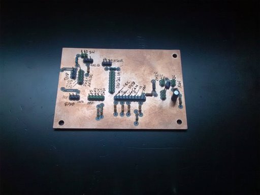
After a final check the schematic is expected following the previous tests done with wires and breadboards so the final PCB prototype has been milled as shown in the images below.

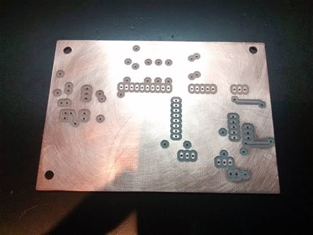
As shown in the final circuit assembled image, only the control components as soldered on the board (mainly the various pull-up resistors). As the board should be fit in the Meditech box and connected to the elements installed at different distances, all the other components are wires with connectors.
Installation
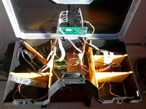
The following images shows how the board and the connections are set inside the box. The control components (LCD, LED status, IR Sensore and calibration potentiometer) are on the top side of the lid, accessible during the normal usage as it should remain closed (and possibly locked). The only two parts that remain inside of the box are the temperature sensor put in the RPImaster ares (the Raspberry-PI 2 main unit) and the can connection that is controled by the board. A couple of flat cables connect this control panel interface board to the ChipKit PI and another flat cable connects the board to the Raspberry PI GPIO for the IR sensor.

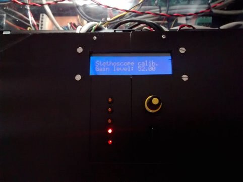
Final view
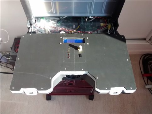
The following images shows the final view of the control panel installed on the top side of the lid. The areas - actually empty - on both sides of the lid surface will include the plugs to connect the diagnostic probes, actually under construction.
Top Comments