element14 Community
element14 Community
    Register Log In
  • Site
  • Search
  • Log In Register
  • Community Hub
    Community Hub
    • What's New on element14
    • Feedback and Support
    • Benefits of Membership
    • Personal Blogs
    • Members Area
    • Achievement Levels
  • Learn
    Learn
    • Ask an Expert
    • eBooks
    • element14 presents
    • Learning Center
    • Tech Spotlight
    • STEM Academy
    • Webinars, Training and Events
    • Learning Groups
  • Technologies
    Technologies
    • 3D Printing
    • FPGA
    • Industrial Automation
    • Internet of Things
    • Power & Energy
    • Sensors
    • Technology Groups
  • Challenges & Projects
    Challenges & Projects
    • Design Challenges
    • element14 presents Projects
    • Project14
    • Arduino Projects
    • Raspberry Pi Projects
    • Project Groups
  • Products
    Products
    • Arduino
    • Avnet & Tria Boards Community
    • Dev Tools
    • Manufacturers
    • Multicomp Pro
    • Product Groups
    • Raspberry Pi
    • RoadTests & Reviews
  • About Us
    About the element14 Community
  • Store
    Store
    • Visit Your Store
    • Choose another store...
      • Europe
      •  Austria (German)
      •  Belgium (Dutch, French)
      •  Bulgaria (Bulgarian)
      •  Czech Republic (Czech)
      •  Denmark (Danish)
      •  Estonia (Estonian)
      •  Finland (Finnish)
      •  France (French)
      •  Germany (German)
      •  Hungary (Hungarian)
      •  Ireland
      •  Israel
      •  Italy (Italian)
      •  Latvia (Latvian)
      •  
      •  Lithuania (Lithuanian)
      •  Netherlands (Dutch)
      •  Norway (Norwegian)
      •  Poland (Polish)
      •  Portugal (Portuguese)
      •  Romania (Romanian)
      •  Russia (Russian)
      •  Slovakia (Slovak)
      •  Slovenia (Slovenian)
      •  Spain (Spanish)
      •  Sweden (Swedish)
      •  Switzerland(German, French)
      •  Turkey (Turkish)
      •  United Kingdom
      • Asia Pacific
      •  Australia
      •  China
      •  Hong Kong
      •  India
      •  Japan
      •  Korea (Korean)
      •  Malaysia
      •  New Zealand
      •  Philippines
      •  Singapore
      •  Taiwan
      •  Thailand (Thai)
      •  Vietnam
      • Americas
      •  Brazil (Portuguese)
      •  Canada
      •  Mexico (Spanish)
      •  United States
      Can't find the country/region you're looking for? Visit our export site or find a local distributor.
  • Translate
  • Profile
  • Settings
Sci Fi Your Pi
  • Challenges & Projects
  • Design Challenges
  • Sci Fi Your Pi
  • More
  • Cancel
Sci Fi Your Pi
Blog Meditech: Control panel PCB and circuit installation
  • Blog
  • Forum
  • Documents
  • Files
  • Mentions
  • Sub-Groups
  • Tags
  • More
  • Cancel
  • New
  • Share
  • More
  • Cancel
Group Actions
  • Group RSS
  • More
  • Cancel
Engagement
  • Author Author: balearicdynamics
  • Date Created: 9 Jun 2015 7:59 PM Date Created
  • Views 1280 views
  • Likes 2 likes
  • Comments 11 comments
  • meditech_project
  • alphanumeric_lcd
  • status_led
  • control_panel_assembly
  • pcb
  • calibration_potentiometer
Related
Recommended

Meditech: Control panel PCB and circuit installation

balearicdynamics
balearicdynamics
9 Jun 2015

PCB prototyping

After a final check the schematic is expected following the previous tests done with wires and breadboards so the final PCB prototype has been milled as shown in the images below.

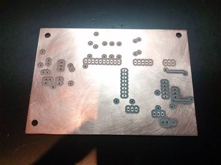
imageimage

As shown in the final circuit assembled image, only the control components as soldered on the board (mainly the various pull-up resistors). As the board should be fit in the Meditech box and connected to the elements installed at different distances, all the other components are wires with connectors.
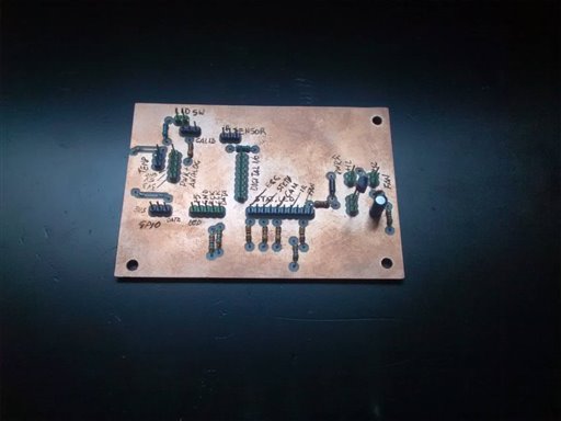
image


Installation

The following images shows how the board and the connections are set inside the box. The control components (LCD, LED status, IR Sensore and calibration potentiometer) are on the top side of the lid, accessible during the normal usage as it should remain closed (and possibly locked). The only two parts that remain inside of the box are the temperature sensor put in the RPImaster ares (the Raspberry-PI 2 main unit) and the can connection that is controled by the board. A couple of flat cables connect this control panel interface board to the ChipKit PI and another flat cable connects the board to the Raspberry PI GPIO for the IR sensor.
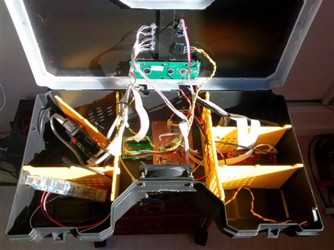
imageimage


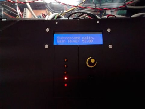
Final view

The following images shows the final view of the control panel installed on the top side of the lid. The areas - actually empty - on both sides of the lid surface will include the plugs to connect the diagnostic probes, actually under construction.
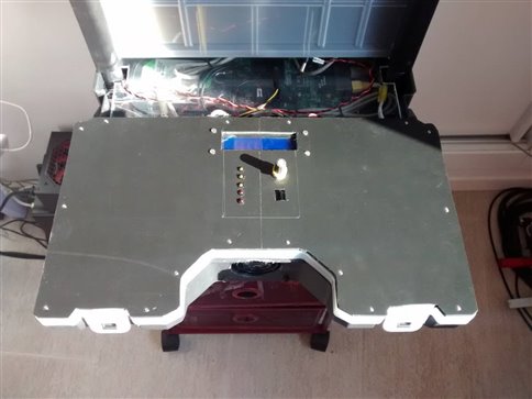
imageimage

  • Sign in to reply

Top Comments

  • mcb1
    mcb1 over 11 years ago in reply to balearicdynamics +2
    Would that be like the axe my grandfather gave me .. I've replaced the handle a couple of times, and the head broke so thats been rerplaced as well... but its the same axe.
  • shabaz
    shabaz over 11 years ago in reply to mcb1 +2
    Hehe. We have a similar saying, called 'Trigger's Broom' : ) https://www.youtube.com/watch?v=BUl6PooveJE
  • fvan
    fvan over 11 years ago +1
    Excellent work as usual, Enrico!
  • screamingtiger
    screamingtiger over 11 years ago in reply to balearicdynamics

    So you have your own mill?  Did you build or buy it?  image

    • Cancel
    • Vote Up 0 Vote Down
    • Sign in to reply
    • More
    • Cancel
  • balearicdynamics
    balearicdynamics over 11 years ago in reply to screamingtiger

    All the boards are milled. Then if needed when I am sure that the PCB proto is 100% correct without problems I send to make 10 pcs to Eurocircuits.

    • Cancel
    • Vote Up 0 Vote Down
    • Sign in to reply
    • More
    • Cancel
  • screamingtiger
    screamingtiger over 11 years ago

    Did you mill this board or have it sent off?  Also what software do you use?  I need to get a PCB software.

    • Cancel
    • Vote Up 0 Vote Down
    • Sign in to reply
    • More
    • Cancel
  • balearicdynamics
    balearicdynamics over 11 years ago

    Board issue


    While testing the final version I have found an issue due a mistake on the schematics (I will correct the related post asap). The pull-up resistor in the LID switch was placed in the wrong place so the result is that the lid switch appears always open instead of detecting the real status. Just done a pcb correction on-the-fly.


    image

    • Cancel
    • Vote Up 0 Vote Down
    • Sign in to reply
    • More
    • Cancel
  • balearicdynamics
    balearicdynamics over 11 years ago in reply to fvan

    Thank you Frederick,


    You'll be my lucky number. I am just adding a comment to the last about an issue I have found in this moment image

    • Cancel
    • Vote Up 0 Vote Down
    • Sign in to reply
    • More
    • Cancel
<>
element14 Community

element14 is the first online community specifically for engineers. Connect with your peers and get expert answers to your questions.

  • Members
  • Learn
  • Technologies
  • Challenges & Projects
  • Products
  • Store
  • About Us
  • Feedback & Support
  • FAQs
  • Terms of Use
  • Privacy Policy
  • Legal and Copyright Notices
  • Sitemap
  • Cookies

An Avnet Company © 2026 Premier Farnell Limited. All Rights Reserved.

Premier Farnell Ltd, registered in England and Wales (no 00876412), registered office: Farnell House, Forge Lane, Leeds LS12 2NE.

Follow element14

  • X
  • Facebook
  • linkedin
  • YouTube