


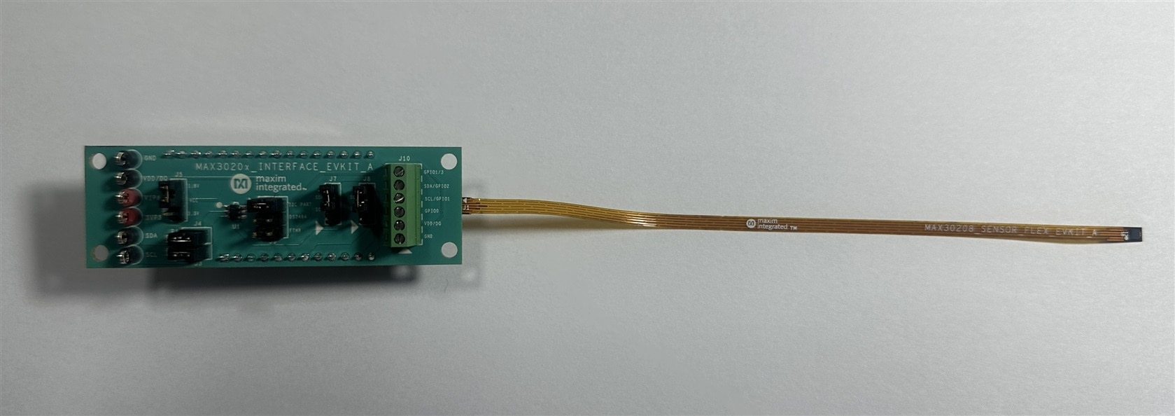
I just received the kit for the Smart Home & Healthcare Design Challenge, which includes the MAX30208 Evaluation Kit. The evaluation system consists of two boards connected through headers: a MAX32630FTHR microcontroller board and a MAX30208 interface board.
The EV system also includes a flexible PCB, with the MAX30208 body temperature sensor located at one end of the flex PCB. At first glance, I did not realize that the sensor was mounted directly on the flex PCB. I initially assumed that the flex PCB was simply a connector used to interface with the microcontroller board. However, after reading the user manual carefully, I realized that the MAX30208 sensor itself is mounted on the flex PCB.
The MAX32630FTHR comes pre-programmed to interface the sensor module with the PC software. Before proceeding with any modifications or development, I was curious to test the sensor using the provided PC software. So, I downloaded the software from the following link: https://www.analog.com/en/resources/evaluation-hardware-and-software/evaluation-boards-kits/max30208evsys.html#eb-overview and followed the user guide to read the sensor data. After installing the software tool, I ran it and got the following interface.
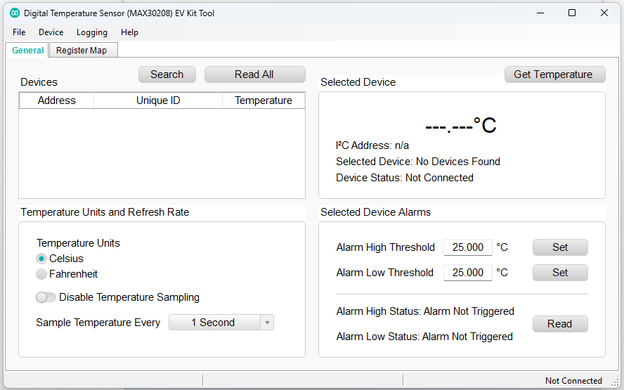
Since I had not yet connected the kit, no device was detected by the software. After connecting the board, the connection status changed, indicating that the board was recognized, but I still could not obtain any temperature data—the temperature sensor was not detected.
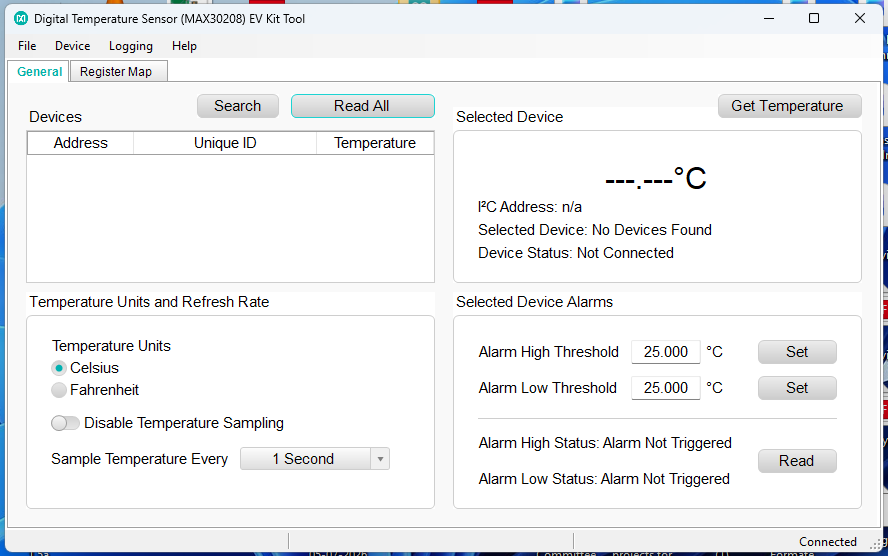
I checked the jumper configuration and tried changing the jumper positions as a troubleshooting step. However, despite these attempts, I was still unable to get any temperature readings from the sensor.
I also checked the SCL and SDA lines and confirmed that both pins are properly pulled high. However, despite verifying the I²C connections, it remains unclear why the temperature sensor is not being detected by the software. In the next step, I will try to connect the sensor board to the Arduino to read the temperature data.
