What is AD8232?
The AD8232 is an integrated signal conditioning block for ECG and other biopotential measurement applications. It is designed to extract, amplify, and filter small biopotential signals in the presence of noisy conditions, such as those created by motion or remote electrode placement. This design allows for an ultralow-power analog-to-digital converter (ADC) or an embedded microcontroller to acquire the output signal easily. The AD8232 can implement a two-pole high-pass filter for eliminating motion artifacts and the electrode half-cell potential. This filter is tightly coupled with the instrumentation architecture of the amplifier to allow both large gain and high-pass filtering in a single stage, thereby saving space and cost. An uncommitted operational amplifier enables the AD8232 to create a three-pole low-pass filter to remove additional noise.
To improve common-mode rejection of the line frequencies in the system and other undesired interferences, the AD8232 includes an amplifier for driven lead applications, such as right leg drive (RLD). The AD8232 includes a fast restore function that reduces the duration of otherwise long settling tails of the high-pass filters. After an abrupt signal change that rails the amplifier (such as a leads off condition), the AD8232 automatically adjusts to a higher filter cutoff. This feature allows the AD8232 to recover quickly, and therefore, to take valid measurements soon after connecting the electrodes to the subject.
The AD8232 SparkFun Module
The AD8232 SparkFun Single Lead Heart Rate Monitor is a cost-effective board used to measure the electrical activity of the heart. This electrical activity can be charted as an ECG or Electrocardiogram and output as an analog reading. ECGs can be extremely noisy, the AD8232 Single Lead Heart Rate Monitor acts as an op amp to help obtain a clear signal from the PR and QT Intervals easily.
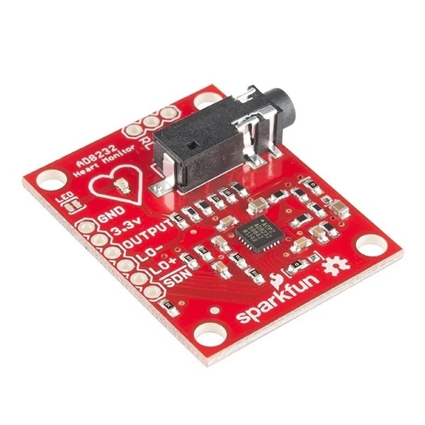
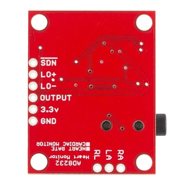
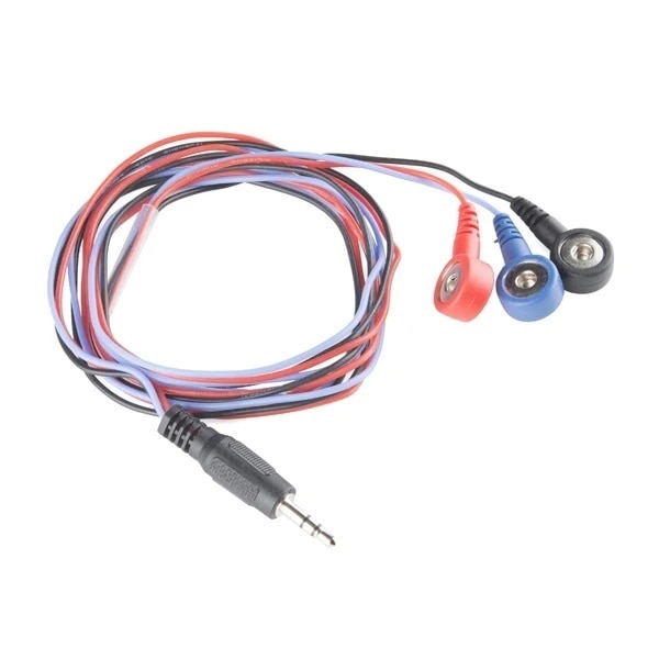
The AD8232 Heart Rate Monitor breaks out nine connections from the IC that you can solder pins, wires, or other connectors to. SDN, LO+, LO-, OUTPUT, 3.3V, GND provide essential pins for operating this monitor with an Arduino or other development board. Also provided on this board are RA (Right Arm), LA (Left Arm), and RL (Right Leg) pins to attach and use your own custom sensors. Additionally, there is an LED indicator light that will pulsate to the rhythm of a heart beat. Biomedical Sensor Pads and Sensor Cable are required to use the heart monitor.
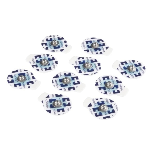
I used the following Cable and Pad with the sensor module.
For primary testing, I used an Arduino Mega board, and the sensor connections to the Arduino board are shown in the following image. I used thin jumper wires to solder the sensor module to the Arduino board.
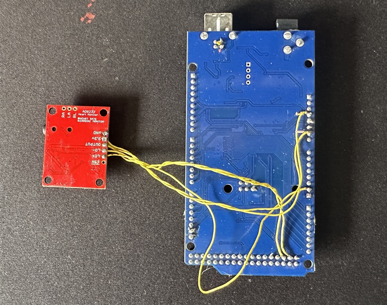
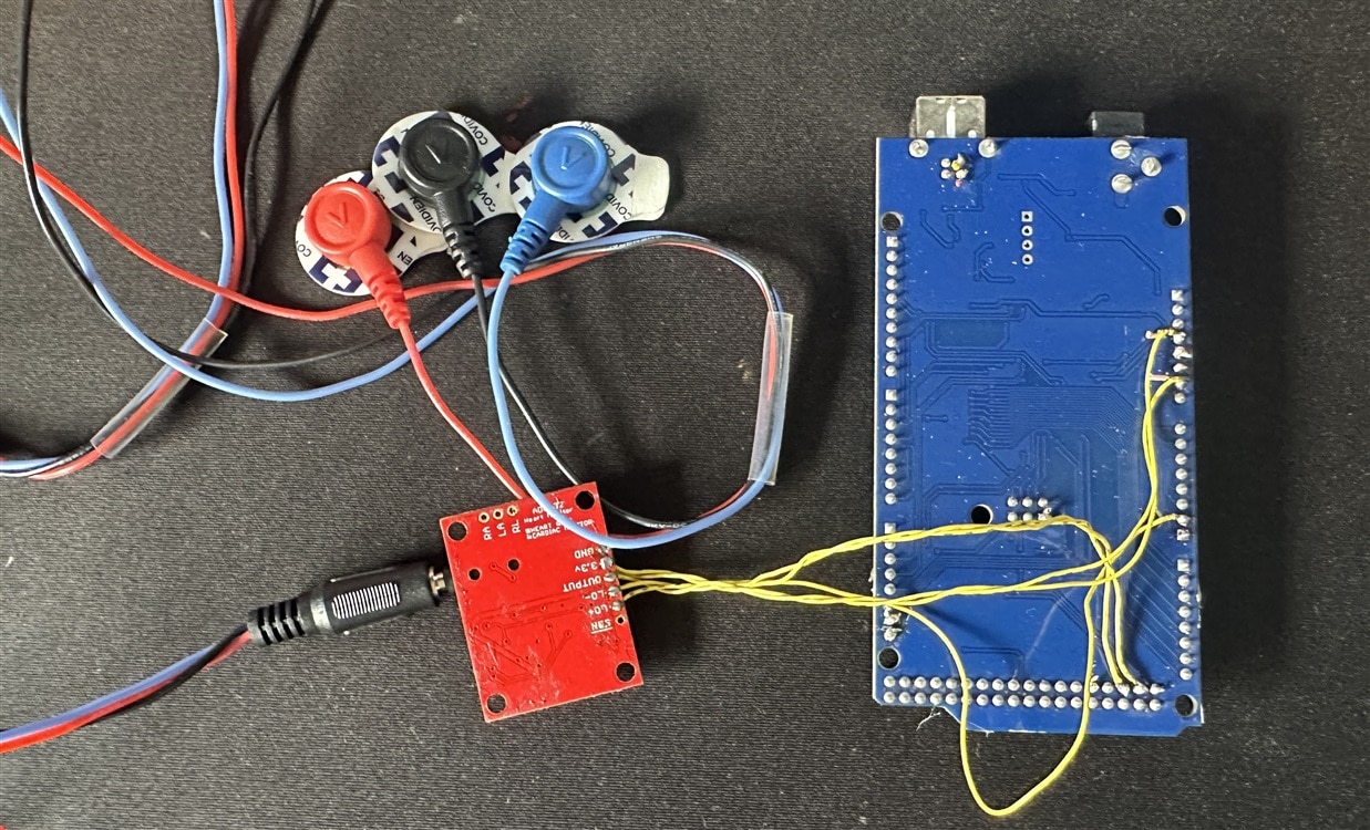
The following connection is made:
I connected five of the board's nine pins to your Arduino. The five pins you need are labeled GND, 3.3v, OUTPUT, LO-, and LO+
| Board Label | Pin Function | Arduino Connection |
| GND | Ground | GND |
| 3.3v | 3.3v Power Supply | 3.3v |
| OUTPUT | Output Signal | A6 |
| LO- | Leads-off Detect - | 48 |
| LO+ | Leads-off Detect + | 50 |
| SDN | Shutdown | Not used |
Sensor Pad Placement
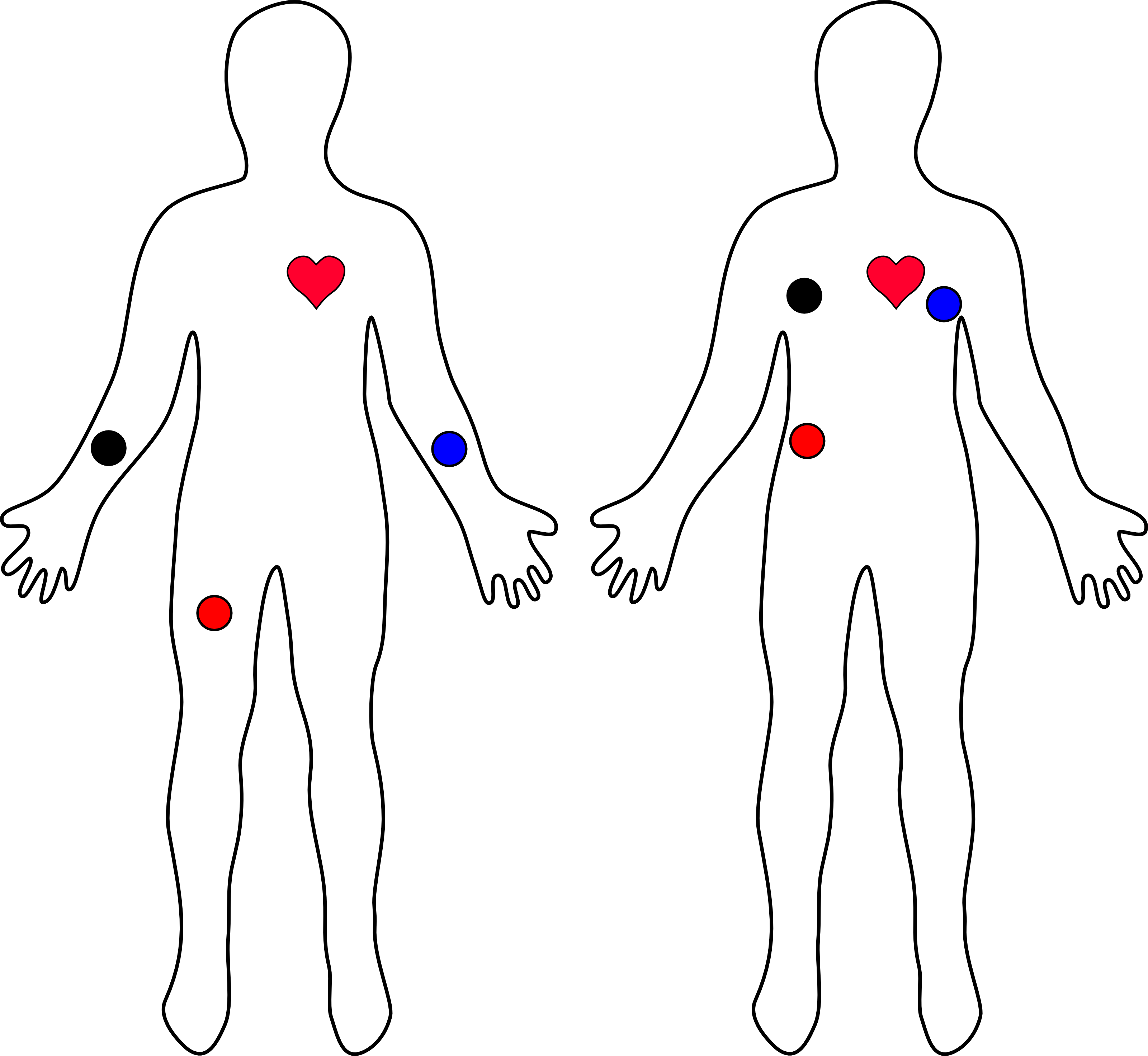
The sensor placement was performed according to the SparkFun recommendation.
The closer to the heart the pads are, the better the measurement. The cables are color-coded to help identify proper placement as shown in the table based on Einthoven's triangle. The sensors can be placed on the forearms and leg as shown on the diagram on the left. Or they can be placed on the chest near the arms and above the right, lower abdomen (i.e. just above the right hip) as shown on the diagram on the right.
| Cable Color | Signal |
| Black | RA (Right Arm) |
| Blue | LA (Left Arm) |
| Red | RL (Right Leg) |
The following code was used for a simple data read:
void setup() {
  // initialize the serial communication:
  Serial.begin(9600);
  pinMode(10, INPUT); // Setup for leads off detection LO +
  pinMode(11, INPUT); // Setup for leads off detection LO -

}

void loop() {

  if((digitalRead(10) == 1)||(digitalRead(11) == 1)){
    Serial.println('!');
  }
  else{
    // send the value of analog input 0:
      Serial.println(analogRead(A0));
  }
  //Wait for a bit to keep serial data from saturating
  delay(1);
}
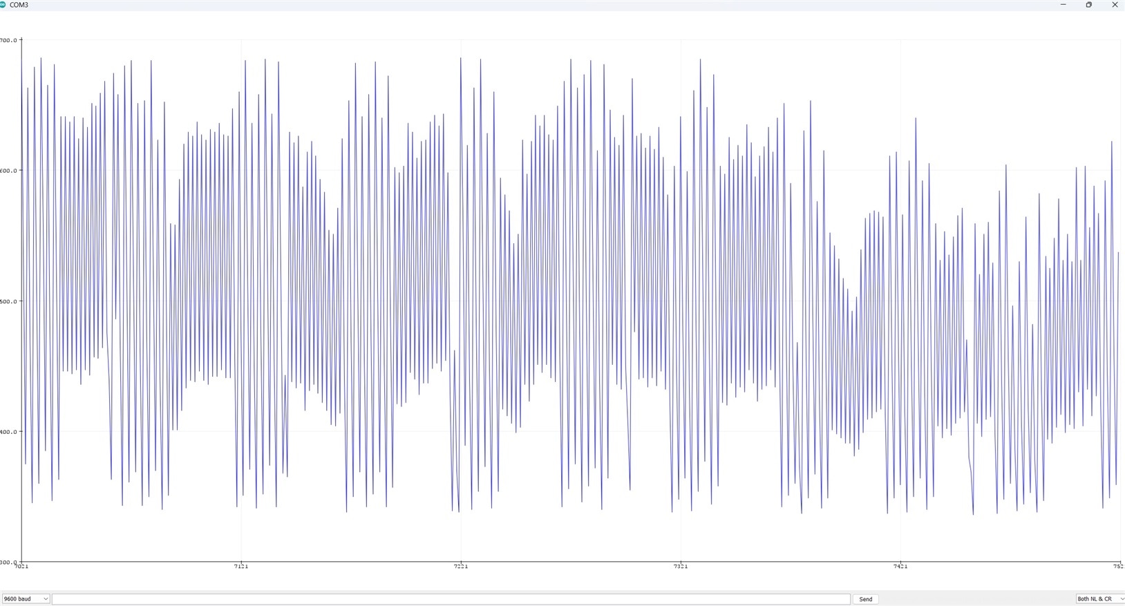
I got the following result from the Arduino Serial Plotter. Maybe it needs some adjustment in the code for a clean graph.