


I hope you are doing well.
I was going to post this yesterday but I was not able to finish it by tomorrow. Also the errors weren't solving that fast and unknown bugs appear. That's why I have to wait till now but I have made some of progress.
I have developed the enclosure and the variable device, if you can say that because it's not that professional but a prototype. That, I will show you in the next post. Also the only thing left is now interfering with the lab view and posting the final project. Thanks to Jo for reminding.
Recap
I was working on project that uses data from multiple resources like breathing data from the radar module, heart beat rate , blood oxygen level to detect the stage of sleep you are in to help you wake up at the right time so you wouldn`t feel tired after you wake up, because wake you up at the right time.I have configured the sensors, the radar module, the Arduino Q, and the ESP32. I have also shown you how the algorithms to make the raw data usable and meaningful worked.
These are the past posts:
Palno & Slemon #1 Introduction
Palno & Slemon #2.1 Configuring and Validating
Palno & Slemon #2.2 Configuring and Validating
Palno & Slemon #3 Building the Algorithm
All firmware sketches, Python processing engines, and interface assets discussed in this build log are packaged here.so you can inspect, flash, or adapt the complete codebase.
The Hardware
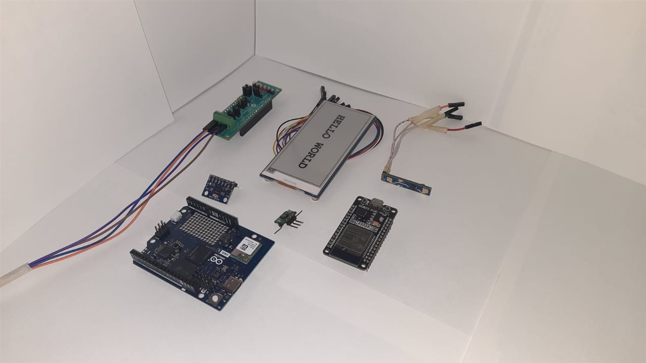
Excluding the batteries
Firstly I was going to build the Palno on PCB but it was not possible as the deadline is too close. If I designed it in 1 hour, then the shipping will not be that fast to get it done. I will be using jumpers and, for the Palno, some small wires only, to connect.
I also will be connecting it to some Bluetooth speakers for waking up the person and also as the apparatus to get the person to sleep effectively by playing some binaural beats.
What the System Must Do: Target Capabilities
Before diving into the breadboards and code, let’s define the functional blueprint. To solve the sleep inertia problem reliably without clinical polysomnography (PSG) scalp electrodes, the system must perform these specific tasks:
- Contactless Thoracic Respiration Tracking: Detect minute chest wall deflections 0.1 to 1.5 mm at distances up to 2.5 meterswithout any cables or body patches, extracting respiration rate (BPM) and breath-to-breath regularity in real time.
- Continuous Peripheral Biometrics via BLE: Measure optical Photoplethysmography (PPG) for Heart Rate and Blood Oxygen Saturation , while capturing 6-axis wrist movement (actigraphy) at 20 Hz20\text{ Hz}20 Hz to track restlessness and sleep postures.
- Ambient Thermal Micro-Climate Monitoring: Track room temperature at 0.05 °C resolution to detect circadian ambient thermal drops and room condition shifts that provoke micro-arousals.
- 30-Second Epoch Sleep Stage Classification: Aggregate multi-modal physiological features into standard 30-second epochs and classify them into Wake, N1 (Drowsiness), N2 (Light Sleep), N3 (Deep Slow-Wave Sleep), and REM (Dream Sleep).
- Acoustic Brainwave Entrainment: Generate binaural auditory beats that dynamically adapt to the user's detected state delivering Delta beats 5hz to 6hz to ease sleep onset and an Alpha/Beta ascending sweep to stimulate morning arousal.
- Intelligent Light-Sleep Awakening: Calculate the optimal waking moment within a customizable morning window, firing the alarm exclusively during N1 or N2 light sleep while forbidding wake-ups during N3 deep sleep.
- Physical Shake-to-Dismiss Alarm Mechanism: Ensure the user is physically alert by requiring active wrist shaking 10 consecutive movements detected by the wearable's accelerometer before the acoustic alarm silences.
- Dual Real-Time Interfaces: Render a local Web UI dashboard served directly by the bedside unit for live viewing, while streaming a continuous Wi-Fi TCP data feed formatted for NI LabVIEW clinical charts and long-term storage.
Let’s explore how each capability was implemented, wired, and debugged on the bench.
Hardware Architecture and Prototype Assembly
The system consists of two primary hardware nodes: the bedside Slemon station and the Palno wrist wearable.
The bedside Slemon station is built around the Arduino Uno Q. It connects directly to an HLK-LD2410 24 GHz millimeter-wave FMCW radar over hardware UART, a MAX30208 digital temperature sensor over I2C, and a 3.5 inch E-Ink display over SPI. The Uno Q contains an STM32 core running Zephyr RTOS that handles real-time peripheral capture, and a Qualcomm Linux core that runs our Python signal processing engines. Internal communication between the two cores is managed through the Arduino RouterBridge framework using lightweight binary RPC calls.
The Palno wearable is built on an ESP32 WROOM DA board. It interfaces with a MAX30102 optical sensor to measure pulse rate and blood oxygen levels, and an MPU6050 six-axis inertial measurement unit to capture actigraphy and wrist orientation. The ESP32 operates as a low-power Bluetooth Low Energy peripheral, packaging sensor readings into custom GATT characteristics and advertising them directly to the bedside unit.
Excluding the batteries, my original plan was to manufacture Palno on a custom printed circuit board. But with the challenge deadline fast approaching, turnaround times made that impossible. Even if I completed the schematic and routed the board in an afternoon, international fabrication and courier shipping would have taken over ten days.
Instead, I opted for a hands-on prototyping approach using breadboards, flexible jumpers, and small hookup wires. While less compact than a production wearable, this setup allowed rapid component testing and zero down-time waiting for postal deliveries.
For sound delivery, rather than burdening the bedside node with bulky analog amplifier circuitry, the system pairs via Bluetooth or standard line-out to external stereo speakers to play synthesized binaural tracks.
Complete Wiring Connections
If you are following along with the schematics here are the exact pin connections used on the bench:
Slemon Bedside Node (Arduino Uno Q):
- HLK-LD2410 Radar TX connects to Pin D0 (USART1 RX, configured at 256000 baud)
- HLK-LD2410 Radar RX connects to Pin D1 (USART1 TX)
- MAX30208 Temperature SCL connects to Pin D20 (I2C1 SCL clock line)
- MAX30208 Temperature SDA connects to Pin D21 (I2C1 SDA data line, address 0x50)
- 3.5 inch E-Ink Display BUSY connects to Pin D4
- 3.5 inch E-Ink Display RESET connects to Pin D5
- 3.5 inch E-Ink Display D/C connects to Pin D6
- 3.5 inch E-Ink Display CS connects to Pin D7
- 3.5 inch E-Ink Display SCK connects to Pin D13
- 3.5 inch E-Ink Display DIN connects to Pin D11
- Power rails: 5V supply for the radar module, 3.3V for the temperature sensor and display, with a shared ground.
Palno Wearable Node (ESP32 WROOM DA):
- MAX30102 SCL connects to Pin GPIO22 (Hardware I2C SCL)
- MAX30102 SDA connects to Pin GPIO21 (Hardware I2C SDA)
- MAX30102 INT connects to Pin GPIO19 (Data-ready interrupt)
- MPU6050 SCL connects to Pin GPIO22 (Shared I2C bus)
- MPU6050 SDA connects to Pin GPIO21 (Shared I2C bus)
- MPU6050 INT connects to Pin GPIO18 (Motion wake interrupt)
- Power rails: Regulated 3.3V and ground from the onboard voltage regulator.
Bench Notes: Debugging the Dual-Core Arduino Uno Q
Working with the Arduino Uno Q reveals an interesting dual-core architecture: an STM32 microcontroller managing real-time peripheral tasks alongside a Qualcomm Linux system handling computation. However, navigating the interactions between these two environments required troubleshooting several undocumented quirks.
Pin Mapping and the Serial versus Monitor Trap
When I initially powered up the Uno Q, the sketch compiled cleanly, but the App Lab serial monitor remained completely blank.
On the Uno Q, standard Serial.print commands are routed directly to the physical header pins D0 and D1. If you use Serial.println, your data goes out over the hardware UART pins instead of the USB debug console! To route telemetry back to your computer's USB terminal, you must use the Monitor object. Redefining Serial resolves this cleanly across all libraries:
#define Serial Monitor

void setup() {
    Monitor.begin(115200);
    Serial.println("[SLEMON] Bootstrapping real-time sensor engine...");
}
Locating the Radar on Hardware Serial1
Because pins D0 and D1 route USART1 on the STM32 core running Zephyr RTOS, the radar driver must connect to Serial1, configured strictly for 256000 baud:
// Correct initialization in sketch.ino (see ZIP archive)
radar_init(&Serial1, 256000);
Assigning Serial2 or standard Serial leaves the radar buffer empty because the physical bytes are arriving on USART1.
The D20 and D21 I2C Orientation
Early temperature readings consistently returned error codes (-999.0 C). On typical Arduino pinouts, SDA and SCL positions can vary between revisions. On the Uno Q:
- Pin D20 is SCL (Clock)
- Pin D21 is SDA (Data)
I had reversed them on the breadboard. Swapping the jumpers and running an automatic bus scanner immediately detected the MAX30208 at address 0x50.
Resolving the Missing dtostrf Function in Zephyr ARM GCC
During compilation of the E-Ink display routine, the build system halted with an error indicating that dtostrf was not declared in scope.
The function dtostrf is a legacy 8-bit AVR routine that does not exist in standard 32-bit ARM GCC libraries under Zephyr. Rather than importing bulky string conversion libraries, I updated eink_display.h to use standard C++ streaming via display.print(floatValue, decimals).
Contactless Thoracic Respiration Detection: Radar Signal Processing
To measure breathing without touching the subject, the bedside Slemon unit uses an HLK-LD2410 24 GHz Frequency-Modulated Continuous-Wave radar. As validated by J. Vargas et al. in their paper "Contactless Respiration and Heart Rate Monitoring Using mmWave FMCW Radar" (IEEE Transactions on Biomedical Engineering, 2019), micro-Doppler phase shifts can resolve chest expansions as subtle as 0.1 mm.
The radar divides its detection field into 9 range gates (0.75 m each). The STM32 core runs an uninterrupted, non-blocking binary Finite State Machine that ingests 20 Hz data frames looking for the 4-byte frame preamble (0xF4, 0xF3, 0xF2, 0xF1) and termination flags (0xF8, 0xF7, 0xF6, 0xF5).
When presence is detected at gate , the stationary energy Estat and moving energy Emov are converted into a composite displacement index. Because radar reflections attenuate with distance following the radar range equation, we apply a distance normalization formula:
I =Eg.(R/R0)^2
where RRR is the measured distance to the torso and R0=100 cm serves as our baseline reference distance.
To separate chest movement from background clutter such as walls, curtains, or airflow, the Python engine on the Qualcomm core maintains an adaptive 10th-percentile baseline noise buffer:
B=Percentile10({St}t=−3000)
A valid breath cycle is counted when the detrended amplitude (I−B)(I - B)(I−B) crosses an adaptive physiological threshold:
Threshold=max(5.0,0.35⋅(Percentile90−B))
# Respiration peak detector from slemon_app/python/breath_engine.py
def process_radar_frame(self, target_detected, target_dist_cm, static_energy):
    if not target_detected:
        return None

    normalized_intensity = static_energy * ((target_dist_cm / 100.0) ** 2)
    self.buffer.append(normalized_intensity)

    baseline = np.percentile(self.buffer, 10)
    detrended = normalized_intensity - baseline

    if detrended > self.dynamic_threshold and not self.in_breath:
        self.in_breath = True
        peak_time = time.time()
        interval = peak_time - self.last_peak_time
        if 1.5 <= interval <= 6.0:  # Valid human respiratory window: 10 to 40 BPM
            bpm = 60.0 / interval
            self.last_peak_time = peak_time
            return bpm
    elif detrended < (self.dynamic_threshold * 0.4):
        self.in_breath = False
    return None
Sleep Stage Neurobiology and the 30-Second Classification Engine
Understanding sleep staging requires looking at the autonomic nervous system. As documented in The AASM Manual for the Scoring of Sleep and Associated Events by R. B. Berry et al. (American Academy of Sleep Medicine, 2012), sleep is not uniform; it progresses through repeating 90 to 110 minute ultradian cycles.
The medical reason people feel disoriented after waking up a phenomenon known as Sleep Inertia, thoroughly reviewed by P. Tassi and A. Muzet in "Sleep Inertia" (Sleep Medicine Reviews, 2000)—is that high concentrations of adenosine remain bound to cortical receptors when slow-wave, synchronized Delta waves (0.5 to 4 Hz) are interrupted during Stage N3 deep sleep. Waking from N3 causes cognitive sluggishness that can last over 45 minutes.
Conversely, waking from Stage N1 or N2 light sleep finds the thalamocortical networks primed for alertness.
Differentiating Sleep Stages Without EEG Scalp Electrodes
Without home EEG equipment, how can we reliably tell these stages apart?
The key insight lies in respiratory variability. In N3 deep sleep, respiration is governed by primitive metabolic pacemakers in the brainstem, producing very steady, periodic breathing. During REM sleep, skeletal muscles are paralyzed, but emotional bursts from the limbic system make breathing irregular.
Every 30 seconds, the classification engine calculates the Coefficient of Variation across the respiration buffer:
CoVRR = σRR/ BB
where σRR is the standard deviation of breath-to-breath intervals and BB is their mean.
# Hierarchical classification tree from slemon_app/python/sleep_classifier.py
def classify_30s_epoch(features):
    # Rule 1: Sustained actigraphy or gross radar disturbance indicates Wake
    if features.mean_disturbance > 50 or features.mean_dyn_accel > 0.10:
        return "WAKE"

    # Rule 2: Absence of vital signs indicates an empty bed
    if features.breath_count < 2 and features.hr_valid_ratio < 0.3:
        return "WAKE"

    # Rule 3: Split between regular NREM sleep and irregular REM/N1 sleep
    if features.resp_cov > 0.12:
        rem_score = 0
        if features.twitch_count >= 2:          rem_score += 2
        if features.hr_cov > 0.04:              rem_score += 1
        if features.mean_disturbance < 10:      rem_score += 1
        if features.time_since_sleep_onset > 60: rem_score += 1

        return "REM" if rem_score >= 4 else "N1"

    else:
        depth_score = 0
        if features.resp_rate < 14.0:             depth_score += 1
        if features.resp_cov < 0.05:              depth_score += 1
        if features.mean_hr < features.hr_floor:  depth_score += 1
        if features.hr_cov > 0.06:                depth_score += 1
        if features.mean_disturbance < 5.0:       depth_score += 1
        if features.epochs_still > 10:            depth_score += 1

        return "N3" if depth_score >= 4 else "N2"
To eliminate temporary signal noise, classifications pass through a 5-epoch (2.5-minute) rolling majority window that filters out physiologically impossible transitions, such as jumping directly from active Wake into deep N3 sleep.
Acoustic Brainwave Entrainment and the Waking Sequence
To help users fall asleep and wake up naturally, the system incorporates acoustic brainwave entrainment using binaural beats, as demonstrated by J. D. Lane et al. in "Binaural Auditory Beats Affect Vigilance Performance and Mood" (Physiology & Behavior, 1998).
When two slightly different pure audio tones are presented separately to each ear, the brainstem perceives a phantom modulation equal to the frequency difference:
Δf= |fleft - fright |
For instance, playing a 200 Hz sine wave in the left ear and a 204 Hz sine wave in the right ear produces an apparent 4 Hz Theta beat.
- Sleep Onset Induction: When the system detects prolonged N1 restlessness, it plays a soft Δf=2.5 Hz Delta beat on a 150 Hz carrier tone to encourage slow-wave relaxation.
- The Smart Waking Window: Within the user-selected wake window (for example, 6:30 AM to 7:00 AM), the classifier evaluates each 30-second epoch. The moment it detects N1 or N2 Light Sleep, it begins waking the user.
- Frequency Ramp: The waking sequence starts with an Alpha tone Δf=10 Hz at 10 percent volume, transitioning smoothly over two minutes into an alert Beta frequency Δf=16 Hz at 60 percent volume.
Live Bench Demonstrations: Serial Logs, Web Dashboard, and Display Updates
To verify our hardware integration, I ran functional tests on my bench to confirm that raw sensor streams are properly captured by the microcontrollers, formatted, and displayed across our visual interfaces.
Serial Monitor Telemetry Output
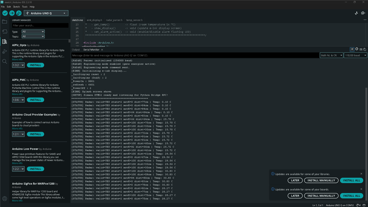
When the Arduino Uno Q boots up, the STM32 Zephyr firmware immediately performs an internal bus scan to confirm connected peripherals, synchronizes with the radar receiver state machine, and begins printing periodic debug telemetry packets:
[BOOT] Arduino Uno Q Multi-Core Slemon Engine Starting...
[I2C] Scanning bus D20/D21... Found 0x50 (MAX30208 Digital Temp)
[RADAR] Serial1 bound at 256000 baud. Waiting for frame sync...
[RADAR] Sync established! Gate=2 | Range=142cm | MoveEnergy=18 | StaticEnergy=64
[BREATH] Instantaneous Respiration: 15.6 BPM | Intensity=128.4 | Filtered=OK
[TEMP] MAX30208 Core Temperature: 24.25 C
[ROUTER_BRIDGE] Telemetry packet dispatched to Linux python core.
[PALNO] BLE Central Connected to ESP32 Wearable (RSSI: -64 dBm)
[PALNO] HR=72 BPM | SpO2=98% | Accel=[0.02g, 0.01g, 0.99g]
This confirmed that the D20/D21 pin orientation was correct, the MAX30208 was successfully reading temperature down to two decimal places, and the radar was actively tracking range and reflected gate energies without dropping frames.
3.5 Inch Display Refresh
In the video demonstration below, you can see the screen cycling through its operational views:
Live Web UI Dashboard and Movement Detection
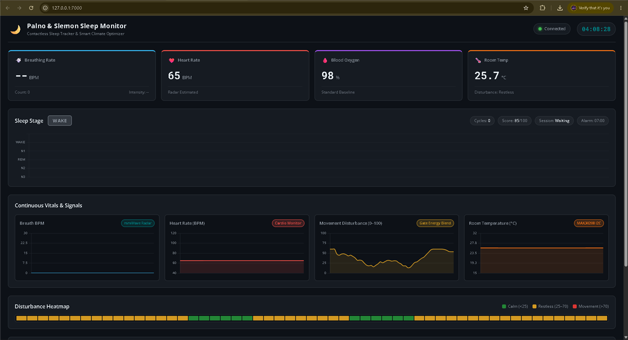
The Python service running on the Uno Q's Qualcomm Linux core hosts a lightweight Socket.IO server on port 7000. Accessing http://<uno-q-ip>:7000 from any browser on the local network loads our real-time monitoring interface.
In this demonstration, you can see how the web dashboard captures and displays movement:
- When sitting still in front of the radar, the distance-normalized intensity signal forms steady, cyclical waves corresponding to chest movement, with the estimated breaths per minute remaining stable.
- When physical movement occurs—such as shifting in a chair or moving hands in front of the unit—the dashboard immediately registers the surge in moving energy across the radar gates.
- The web interface dynamically flags the movement event, showing how motion disturbance is separated from genuine micro-chest breathing deflections.
Clinical Data Logging: Wi-Fi Integration with NI LabVIEW
For in-depth analysis and long-term sleep logging, the bedside unit connects to National Instruments LabVIEW over Wi-Fi.
The Python service runs an internal TCP server on port 5005. Once LabVIEW connects across the local network, the server streams clean JSON telemetry packets every 2 seconds:
{
  "timestamp": 1729792014.2,
  "respiration_bpm": 15.4,
  "radar_gate": 2,
  "radar_distance_cm": 138,
  "ambient_temp_c": 24.15,
  "heart_rate_bpm": 64,
  "spo2_percent": 98,
  "wrist_motion_g": 0.018,
  "classified_stage": "N2",
  "sleep_depth_score": 3
}
Final Thoughts and Next Steps
Building Palno and Slemon has been a rewarding challenge in embedded sensor fusion—from parsing high-speed mmWave radar frames on an STM32 core to bridging live telemetry into Python and streaming it over Wi-Fi.
The next and final post will bring everything together for the challenge finale:
- Complete screenshots of the multi-channel LabVIEW front panel showing overnight trend lines.
- Building the final enclosure and the wearable..
- Full GitHub repository release containing all schematics, code, and documentation.
Thank you for reading and following along with the build! I would love to hear your feedback, suggestions, and thoughts in the comments below.