


1. Project Motivation
In the realm of embedded systems and IoT, health-monitoring devices are increasingly shifting from complex desktop setups to portable, edge-computed instruments. The primary motivation behind this project was to build a standalone, highly responsive, and visually professional biomedical monitor capable of tracking vital signs in real-time—specifically Heart Rate (HR), Blood Oxygen Saturation (SpO2), and ambient/body temperature.
Standard hobbyist biometric displays often suffer from visual shortcomings: flickering text, choppy or boxy pixelated waveforms that resemble rigid rectangles rather than physiological pulses, and ghosting artifacts. This project aimed to solve those issues by implementing an advanced double-buffering graphics architecture using sprites, sophisticated digital filtering, and smooth signal interpolation to achieve a clean, clinical-grade aesthetic reminiscent of professional hospital monitors.
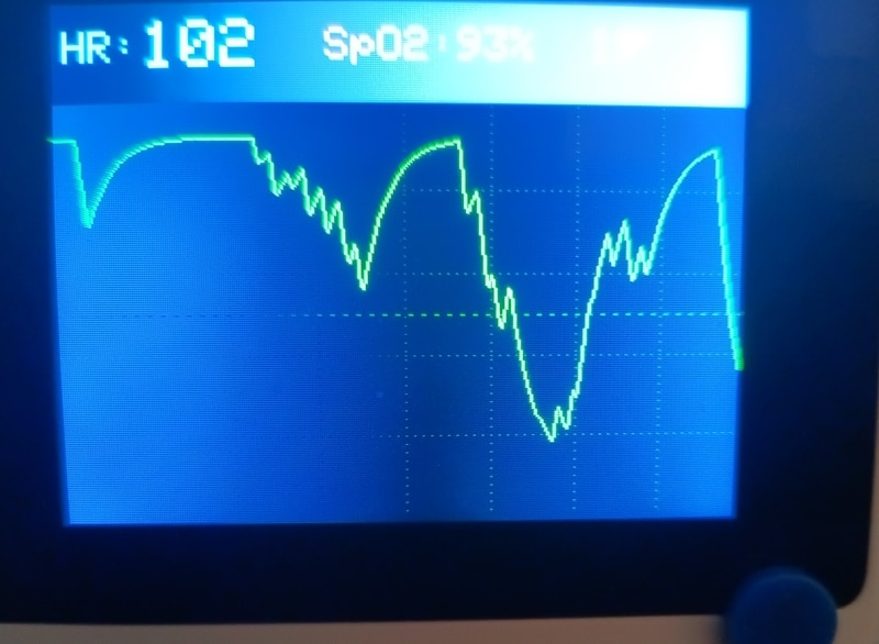
2. Detailed Description of the Wio Terminal
At the heart of this project is the Seeed Wio Terminal, an ATSAMD51-based microcontroller with wireless connectivity, packed into a compact, all-in-one enclosure featuring a 2.4-inch LCD screen, an onboard light sensor, an infrared emitter/receiver, physical buttons, and a 40-pin Raspberry Pi-compatible GPIO header.
-
Microcontroller Core: Powered by a Microchip ATSAMD51P19 ARM Cortex-M4F running at 120 MHz, providing ample processing power for real-time digital signal processing (DSP) and graphical rendering.
-
Display: A crisp 320x240 pixel IPS LCD screen capable of vibrant color reproduction and high-speed updates via the
TFT_eSPIlibrary. -
Ecosystem & Usability: Its form factor includes built-in buttons and a 5-way switch, making it an ideal platform for standalone desktop instrumentation without requiring an external computer interface during operation.

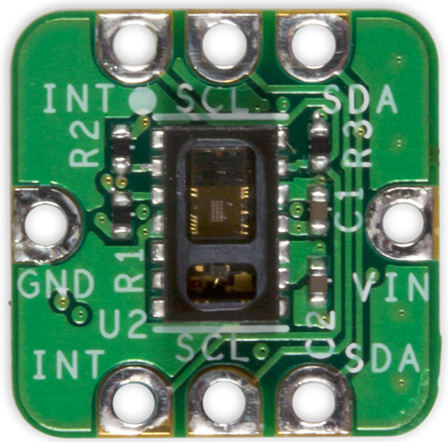
The MAX30102 (MAXREFDES117 EK) optical sensor acts as the front-end biometric acquisition unit. It houses internal LEDs (Red, IR, and Green) and a sensitive photodetector to measure light absorption changes caused by pulse blood flow through the capillaries (Photoplethysmography - PPG). Additionally, it features an integrated temperature sensor for accurate die-temperature readings.
3. Step-by-Step Implementation Guide
Step 1: Hardware Integration & I2C Wiring
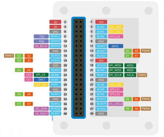
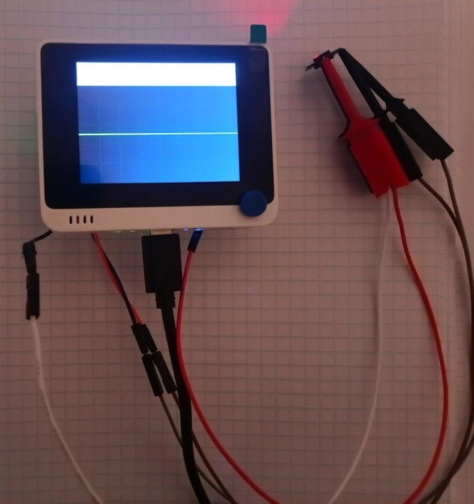
The MAX30105 sensor communicates via the I2C protocol. It is wired directly to the Wio Terminal's internal I2C bus and power rails:
-
VIN connected to 3.3V / 5V power supply.
-
GND connected to System Ground.
-
SDA connected to the I2C data line (SDA / D20).
-
SCL connected to the I2C clock line (SCL / D21).
Step 2: Eliminating Flicker via Dual-Sprite UI Architecture
To prevent screen tearing, text ghosting, and ugly refresh rectangles (fillRect artifacts), direct drawing to the physical screen was abandoned. Instead, the application utilizes TFT_eSprite for double-buffering:
-
headerSprite(320x45 pixels): Renders the top status bar containing real-time metrics (HR, SpO2, and Temperature) entirely in RAM before pushing it to the screen in a single, flicker-free operation. -
waveGraph(320x190 pixels): Dedicated memory buffer that handles the scrolling waveform area independently from text updates.
Step 3: Signal Processing & Filtering
Raw optical data from photoplethysmography is notoriously susceptible to ambient noise and motion artifacts. The firmware implements:
-
DC Removal High-Pass Filter: Separates the pulsatile AC component from the massive DC baseline caused by static tissue absorption.
-
Threshold-based Finger Detection: Instantly recognizes when a finger is placed or removed from the sensor (
rawIRthresholds) without lagging or throwing false calibrations. -
Moving Average & Peak Detection: Tracks systolic peaks dynamically to calculate stable rolling averages for heart rate (
beatAvg) and estimate blood oxygen saturation (SpO2).
Step 4: Organic Waveform Rendering & Grid Integration
To eliminate the rigid, boxy "staircase" look common in basic microcontrollers, the waveform engine uses:
-
Interpolation and Smoothing: Neighboring points in the 320-point history array are blended using linear interpolation, transforming sharp pixel steps into smooth, organic physiological curves.
-
Medical-Grade Grid & Baseline: A faint light-green background grid and a central baseline are rendered directly into the waveform buffer to give it an authentic clinical monitor appearance.
-
Dynamic Horizontal Stretching: Fine-tuned sample buffers ensure the pulse wave spans the entire width of the screen gracefully.
Step 5: Multi-Parameter UI Integration
The top header cleanly displays:
-
HR (Heart Rate): Highlighted in cyan with large typography, showing real-time bpm or status indicators (No finger, Search).
-
SpO2: Tracked in magenta percentage values.
-
Temperature: Read directly from the MAX30105 internal sensor and displayed in yellow.
4. Overview of Current Screens and States in the Code
-
Initialization Error Screen
-
When it occurs: Upon startup, if the Wio Terminal fails to detect the MAX30105 sensor on the I2C bus.
-
Appearance: Red message on a black background: "Error: MAX30105 not found!" and the loop halts in an error state.
-

-
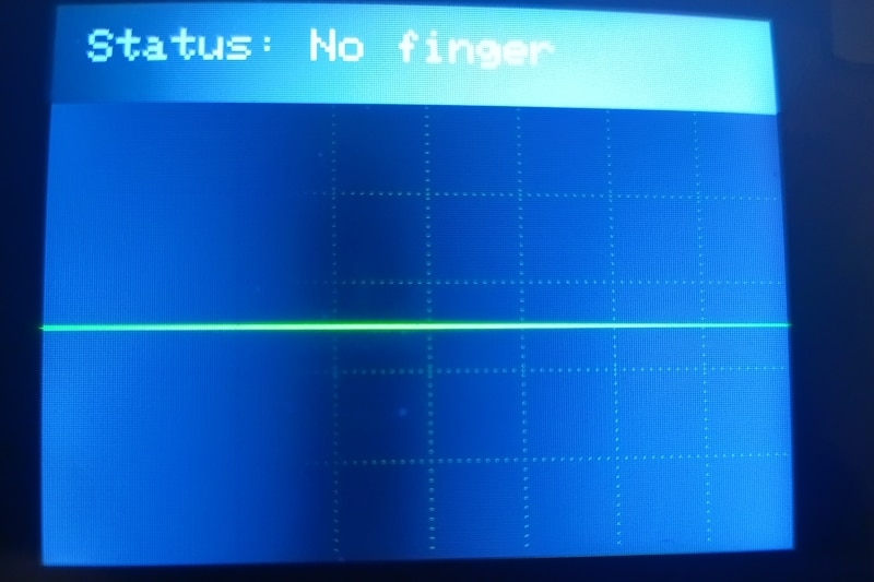
No Finger / Standby State
-
When it occurs: When the device is running, but the user has not placed a finger on the sensor (raw IR value
rawIR < 50000). -
Appearance: The text "No finger" appears in light gray in the upper-left HR section, and a flat center baseline is shown on the waveform. SpO2 and temperature values display an inactive state ("--").
-
-
Calibration Phase
-
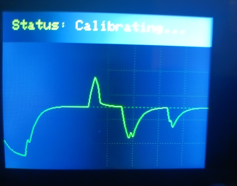
When it occurs: During the first 1.5 seconds after finger placement is detected.
-
Appearance: The yellow text "Calib" is displayed in the HR section. During this time, the digital high-pass filter stabilizes the baseline signal to prevent jumps and errors at the start of the measurement.
-
-
Live Monitoring Screen
-
When it occurs: When a finger is properly placed and the filter has completed calibration.
-
Content:
-
Top Header: Large, legible real-time values – HR (heart rate in cyan), SpO2 (oxygen saturation in magenta), and Temp (temperature from the sensor in yellow).
-
Waveform Area: A real-time, smoothed PPG waveform in green, rendered over a subtle light-green grid and a distinct center baseline.
-
-
5. Logical Flow of the Device (Data Processing Pipeline)
Here is a simplified flowchart showing how the device processes data in every program loop:
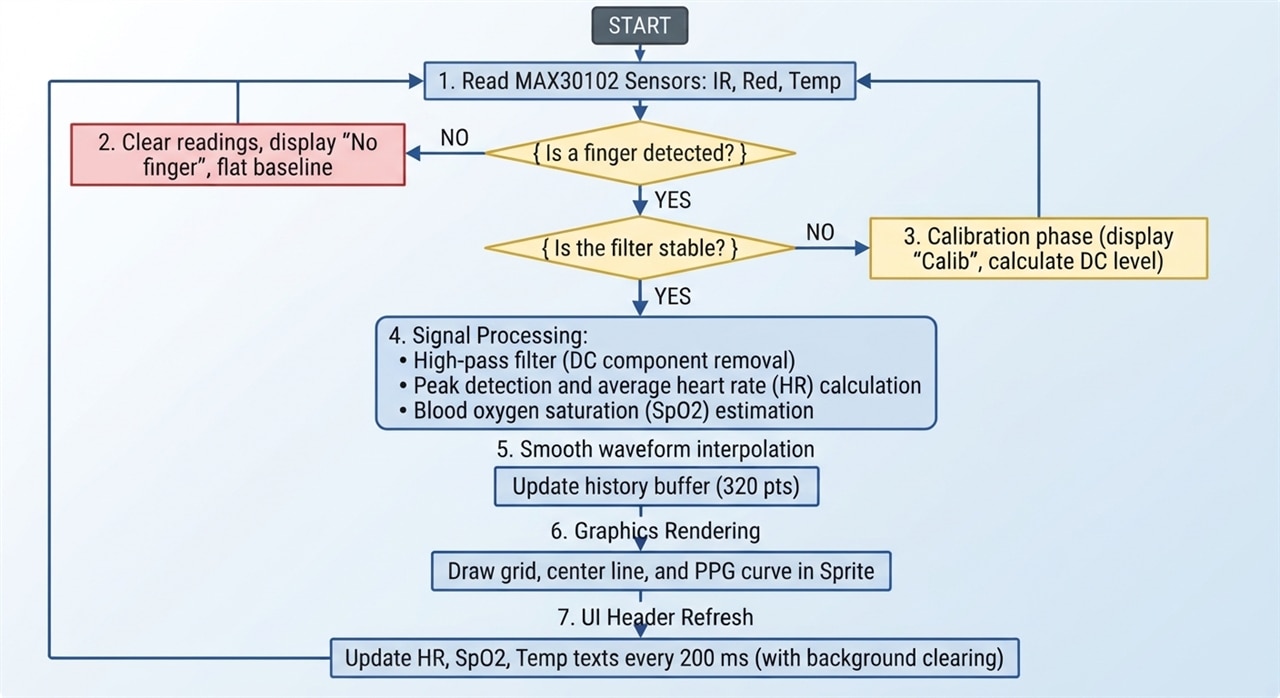
This architecture ensures smooth performance, zero screen flicker (thanks to the double-buffering Sprite technique), and a precise pulse representation reminiscent of professional medical equipment.
6. Code Architecture & Key Components Explained
State Machine & Debouncing (Eliminating UI Flicker)
Optical sensors are sensitive to micro-movements, which can cause raw IR values to fluctuate rapidly around thresholds. To prevent the screen from rapidly switching back and forth ("ping-ponging") between states, the code implements a State Machine with Temporal Debouncing.
-
States:
STATE_NO_FINGER,STATE_CALIBRATING, andSTATE_RUNNING. -
Debounce Logic: A state change must remain stable for at least
300 msbefore the display updates. -
Example: If a finger briefly slips, the system doesn't immediately flash a "No finger" warning; it validates the stability first, ensuring a clean, clinical visual experience.
Signal Processing & High-Pass Filtering
Photoplethysmography (PPG) signals contain a massive DC baseline caused by static tissue light absorption, alongside a tiny AC pulsatile component corresponding to heartbeats.
-
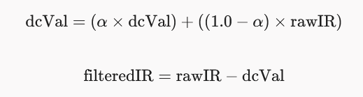
DC Removal: A digital high-pass filter ($alpha = 0.95$) isolates the dynamic AC pulse:
-
Peak Detection: The algorithm tracks local maxima and minima to calculate rolling heart rate averages (
beatAvg) and estimate blood oxygen saturation (SpO2).
Smooth Waveform Interpolation & Double Buffering
To avoid rigid, blocky "staircase" waveforms and screen tearing:
-
TFT_eSprite: The waveform is rendered entirely in RAM using a 320x190 pixel buffer (waveGraph) before being pushed to the IPS screen in a single operation. -
Linear Interpolation: Neighboring points in the 320-point history array are blended (
interpolationSpeed = 0.08), smoothing out sharp pixel jumps into an organic physiological curve accompanied by a medical-grade grid and center baseline.
Artifact Prevention in Dynamic Headers
When metrics change size (e.g., heart rate dropping from 3 digits like 105 down to 2 digits like 98), standard text printing leaves ghosting artifacts from the trailing digits.
-
Dynamic Clearing: The header uses dedicated
fillRectcalls scoped strictly to each metric box (HR, SpO2, Temp) whenever a value or state changes, ensuring zero overlapping text or residual artifacts. -
Layout Tuning: The temperature display is shifted further to the right (
x = 245) to optimize spacing and balance the 320-pixel widescreen layout.
7. Complete Source Code
#include <Arduino.h>
#include <Wire.h>
#include <TFT_eSPI.h>
#include "MAX30105.h"

TFT_eSPI tft = TFT_eSPI();
TFT_eSprite waveGraph = TFT_eSprite(&tft); // RAM buffer for the waveform (width 320, height 190)
MAX30105 particleSensor;

int beatAvg = 0;
const int RATE_SIZE = 8;
byte rates[RATE_SIZE];
byte rateSpot = 0;

float dcVal = 0;
const float alpha = 0.95;
unsigned long fingerTouchTime = 0;
bool isFilterStable = false;

// Device state definitions (prevents UI flickering)
enum DeviceState { STATE_NO_FINGER, STATE_CALIBRATING, STATE_RUNNING };
DeviceState currentDisplayState = STATE_NO_FINGER;
DeviceState rawSensorState = STATE_NO_FINGER;
unsigned long stateDebounceTimer = 0;
const unsigned long debounceDelay = 300; // State must remain stable for 300ms

// Wave history array (320 points)
int waveHistory[320];

// Horizontal wave stretching (interpolation) variables
float targetY = 95;
float currentY = 95;
const float interpolationSpeed = 0.08;

void setup() {
  Serial.begin(115200);
  delay(1000);

  tft.begin();
  tft.setRotation(3); // Landscape screen orientation
  tft.fillScreen(TFT_BLACK);

  // Allocate memory for the waveform sprite (320x190 pixels)
  waveGraph.createSprite(320, 190);

  Wire.begin();

  if (!particleSensor.begin(Wire, I2C_SPEED_FAST)) {
    tft.fillScreen(TFT_BLACK);
    tft.setCursor(15, 50);
    tft.setTextColor(TFT_RED, TFT_BLACK);
    tft.setTextSize(2);
    tft.print("Error: MAX30105 not found!");
    while (1) { delay(10); };
  }

  // Optical sensor configuration
  particleSensor.setup(60, 4, 2, 400, 411, 4096);
  particleSensor.enableDIETEMPRDY();

  // Initialize wave history with center baseline value (95 px)
  for(int i = 0; i < 320; i++) {
    waveHistory[i] = 95;
  }

  // Initial top data header panel background
  tft.fillRect(0, 0, 320, 45, TFT_DARKGREY);
}

void loop() {
  particleSensor.check();

  long rawIR = 0;
  int estimatedSpO2 = 0;
  float filteredIR = 0;
  float currentTemp = 0;
  bool sensorHasFinger = false;

  if (particleSensor.available()) {
    rawIR = particleSensor.getIR();
    long rawRed = particleSensor.getRed();
    particleSensor.nextSample();

    currentTemp = particleSensor.readTemperature();

    // Finger presence detection with thresholds
    if (rawIR > 55000) {
      sensorHasFinger = true;
    } else if (rawIR < 45000) {
      sensorHasFinger = false;
    } else {
      sensorHasFinger = (rawSensorState != STATE_NO_FINGER);
    }

    // Determine raw sensor state
    DeviceState detectedState;
    if (!sensorHasFinger) {
      detectedState = STATE_NO_FINGER;
    } else {
      if (!isFilterStable) {
        detectedState = STATE_CALIBRATING;
      } else {
        detectedState = STATE_RUNNING;
      }
    }

    // Temporal hysteresis (State debounce) – eliminates flickering
    if (detectedState != rawSensorState) {
      rawSensorState = detectedState;
      stateDebounceTimer = millis();
    }

    if ((millis() - stateDebounceTimer > debounceDelay) && (rawSensorState != currentDisplayState)) {
      currentDisplayState = rawSensorState;
      // Force complete header background clear on state change
      tft.fillRect(0, 0, 320, 45, TFT_DARKGREY);

      if (currentDisplayState == STATE_NO_FINGER || currentDisplayState == STATE_CALIBRATING) {
        isFilterStable = false;
        dcVal = 0;
        fingerTouchTime = 0;
        beatAvg = 0;
      }
    }

    // Processing logic based on stable state
    if (currentDisplayState == STATE_NO_FINGER) {
      beatAvg = 0;
      isFilterStable = false;
      dcVal = 0;
      fingerTouchTime = 0;
    } else if (currentDisplayState == STATE_CALIBRATING) {
      if (fingerTouchTime == 0) {
        fingerTouchTime = millis();
        dcVal = rawIR;
      }
      dcVal = (alpha * dcVal) + ((1.0 - alpha) * (float)rawIR);
      if (millis() - fingerTouchTime > 1500) {
        isFilterStable = true;
      }
    } else { // STATE_RUNNING
      static long previousRawIR = rawIR;
      long irDelta = abs(rawIR - previousRawIR);
      previousRawIR = rawIR;

      if (irDelta <= 8000) {
        dcVal = (alpha * dcVal) + ((1.0 - alpha) * (float)rawIR);
        filteredIR = (float)rawIR - dcVal;

        unsigned long currentTime = millis();
        static unsigned long lastBeat = 0;
        static long lastFilteredIR = 0;
        static bool falling = false;
        static float peakValue = 0;

        if (filteredIR > lastFilteredIR) {
          if (falling) falling = false;
          if (filteredIR > peakValue) peakValue = filteredIR;
        } else if (filteredIR < lastFilteredIR) {
          if (!falling && (peakValue - filteredIR > 10.0)) {
            falling = true;

            long delta = currentTime - lastBeat;
            if (delta > 300 && delta < 2000) {
              long beatsPerMinute = 60000 / delta;
              if (beatsPerMinute > 45 && beatsPerMinute < 180) {
                rates[rateSpot++] = (byte)beatsPerMinute;
                rateSpot %= RATE_SIZE;

                beatAvg = 0;
                for (byte x = 0; x < RATE_SIZE; x++) {
                  beatAvg += rates[x];
                }
                beatAvg /= RATE_SIZE;
              }
            }
            lastBeat = currentTime;
            peakValue = filteredIR;
          }
        }
        lastFilteredIR = filteredIR;

        if (rawIR > 100000 && rawRed > 50000) {
          float ratio = (float)rawRed / (float)rawIR;
          float spo2Calc = 110.0 - (25.0 * ratio);

          if (spo2Calc > 95.0 && spo2Calc <= 100.0) estimatedSpO2 = 98;
          else if (spo2Calc > 90.0) estimatedSpO2 = 96;
          else estimatedSpO2 = 93;
        }
      }
    }

    if (currentDisplayState == STATE_RUNNING) {
      int scaled = (int)(filteredIR * 3.5);
      targetY = 95 - scaled;
      targetY = constrain(targetY, 15, 175);
    } else {
      targetY = 95;
    }
  }

  currentY = currentY + (targetY - currentY) * interpolationSpeed;

  for(int i = 0; i < 319; i++) {
    waveHistory[i] = waveHistory[i + 1];
  }
  waveHistory[319] = (int)currentY;

  // --- DRAWING WAVEFORM AND GRID IN MEMORY ---
  waveGraph.fillSprite(TFT_BLACK);

  uint16_t gridColor = 0x01A0;
  uint16_t centerLineColor = 0x0320;

  for (int x = 40; x < 320; x += 40) {
    for (int y = 0; y < 190; y += 4) {
      waveGraph.drawPixel(x, y, gridColor);
    }
  }

  for (int y = 38; y < 190; y += 38) {
    for (int x = 0; x < 320; x += 4) {
      waveGraph.drawPixel(x, y, gridColor);
    }
  }

  for (int x = 0; x < 320; x += 6) {
    waveGraph.drawPixel(x, 95, centerLineColor);
    waveGraph.drawPixel(x + 1, 95, centerLineColor);
  }

  for(int i = 0; i < 319; i++) {
    int y1 = (waveHistory[i] + waveHistory[max(0, i-1)]) / 2;
    int y2 = (waveHistory[i+1] + waveHistory[i]) / 2;

    waveGraph.drawLine(i, y1, i + 1, y2, TFT_GREEN);
  }

  waveGraph.pushSprite(0, 46);

  // --- STABLE HEADER RENDERING (No flickering, updates on value change) ---
  static DeviceState lastRenderedState = (DeviceState)-1;
  static int lastBeatAvg = -1;
  static int lastSpO2 = -1;
  static int lastTempInt = -1;

  bool stateChanged = (currentDisplayState != lastRenderedState);
  if (stateChanged) {
    tft.fillRect(0, 0, 320, 45, TFT_DARKGREY);
    lastRenderedState = currentDisplayState;
    lastBeatAvg = -1;
    lastSpO2 = -1;
    lastTempInt = -1;
  }

  if (currentDisplayState == STATE_NO_FINGER) {
    if (stateChanged) {
      tft.setTextColor(TFT_LIGHTGREY, TFT_DARKGREY);
      tft.setTextSize(2);
      tft.setCursor(15, 12);
      tft.print("Status: No finger");
    }
  }
  else if (currentDisplayState == STATE_CALIBRATING) {
    if (stateChanged) {
      tft.setTextColor(TFT_YELLOW, TFT_DARKGREY);
      tft.setTextSize(2);
      tft.setCursor(15, 12);
      tft.print("Status: Calibrating...");
    }
  }
  else { // STATE_RUNNING
    // 1. HR Display (Full block clear prevents artifacting from 3-digit drops)
    if (beatAvg != lastBeatAvg || stateChanged) {
      lastBeatAvg = beatAvg;
      tft.fillRect(5, 10, 115, 25, TFT_DARKGREY);

      tft.setTextColor(TFT_CYAN, TFT_DARKGREY);
      tft.setTextSize(2);
      tft.setCursor(5, 12);
      tft.print("HR:");

      tft.setTextSize(3);
      tft.setCursor(42, 8);
      tft.print(beatAvg > 0 ? String(beatAvg) : "---");
    }

    // 2. SpO2 Display
    if (estimatedSpO2 != lastSpO2 || stateChanged) {
      lastSpO2 = estimatedSpO2;
      tft.fillRect(125, 10, 110, 25, TFT_DARKGREY);

      tft.setTextColor(TFT_MAGENTA, TFT_DARKGREY);
      tft.setTextSize(2);
      tft.setCursor(125, 12);
      tft.print("SpO2:");

      tft.setCursor(185, 12);
      tft.print(estimatedSpO2 > 0 ? String(estimatedSpO2) + "%" : "--%");
    }

    // 3. Temperature Display (Shifted right to x = 245)
    int tempInt = (int)currentTemp;
    if (tempInt != lastTempInt || stateChanged) {
      lastTempInt = tempInt;
      tft.fillRect(245, 10, 70, 25, TFT_DARKGREY);

      tft.setTextColor(TFT_YELLOW, TFT_DARKGREY);
      tft.setTextSize(2);
      tft.setCursor(245, 12);
      if (currentTemp > 10.0) {
        tft.print(tempInt);
        tft.setTextSize(1);
        tft.print("C");
      }
    }
  }
}
#include <Arduino.h>
#include <Wire.h>
#include <TFT_eSPI.h>
#include "MAX30105.h"
TFT_eSPI tft = TFT_eSPI();
TFT_eSprite waveGraph = TFT_eSprite(&tft); // RAM buffer for the waveform (width 320, height 190)
MAX30105 particleSensor;
int beatAvg = 0;
const int RATE_SIZE = 8;
byte rates[RATE_SIZE];
byte rateSpot = 0;
float dcVal = 0;
const float alpha = 0.95;
unsigned long fingerTouchTime = 0;
bool isFilterStable = false;
// Device state definitions (prevents UI flickering)
enum DeviceState { STATE_NO_FINGER, STATE_CALIBRATING, STATE_RUNNING };
DeviceState currentDisplayState = STATE_NO_FINGER;
DeviceState rawSensorState = STATE_NO_FINGER;
unsigned long stateDebounceTimer = 0;
const unsigned long debounceDelay = 300; // State must remain stable for 300ms
// Wave history array (320 points)
int waveHistory[320];
// Horizontal wave stretching (interpolation) variables
float targetY = 95;
float currentY = 95;
const float interpolationSpeed = 0.08;
void setup() {
Serial.begin(115200);
delay(1000);
tft.begin();
tft.setRotation(3); // Landscape screen orientation
tft.fillScreen(TFT_BLACK);
// Allocate memory for the waveform sprite (320x190 pixels)
waveGraph.createSprite(320, 190);
Wire.begin();
if (!particleSensor.begin(Wire, I2C_SPEED_FAST)) {
tft.fillScreen(TFT_BLACK);
tft.setCursor(15, 50);
tft.setTextColor(TFT_RED, TFT_BLACK);
tft.setTextSize(2);
tft.print("Error: MAX30105 not found!");
while (1) { delay(10); };
}
// Optical sensor configuration
particleSensor.setup(60, 4, 2, 400, 411, 4096);
particleSensor.enableDIETEMPRDY();
// Initialize wave history with center baseline value (95 px)
for(int i = 0; i < 320; i++) {
waveHistory[i] = 95;
}
// Initial top data header panel background
tft.fillRect(0, 0, 320, 45, TFT_DARKGREY);
}
void loop() {
particleSensor.check();
long rawIR = 0;
int estimatedSpO2 = 0;
float filteredIR = 0;
float currentTemp = 0;
bool sensorHasFinger = false;
if (particleSensor.available()) {
rawIR = particleSensor.getIR();
long rawRed = particleSensor.getRed();
particleSensor.nextSample();
currentTemp = particleSensor.readTemperature();
// Finger presence detection with thresholds
if (rawIR > 55000) {
sensorHasFinger = true;
} else if (rawIR < 45000) {
sensorHasFinger = false;
} else {
sensorHasFinger = (rawSensorState != STATE_NO_FINGER);
}
// Determine raw sensor state
DeviceState detectedState;
if (!sensorHasFinger) {
detectedState = STATE_NO_FINGER;
} else {
if (!isFilterStable) {
detectedState = STATE_CALIBRATING;
} else {
detectedState = STATE_RUNNING;
}
}
// Temporal hysteresis (State debounce) – eliminates flickering
if (detectedState != rawSensorState) {
rawSensorState = detectedState;
stateDebounceTimer = millis();
}
if ((millis() - stateDebounceTimer > debounceDelay) && (rawSensorState != currentDisplayState)) {
currentDisplayState = rawSensorState;
// Force complete header background clear on state change
tft.fillRect(0, 0, 320, 45, TFT_DARKGREY);
if (currentDisplayState == STATE_NO_FINGER || currentDisplayState == STATE_CALIBRATING) {
isFilterStable = false;
dcVal = 0;
fingerTouchTime = 0;
beatAvg = 0;
}
}
// Processing logic based on stable state
if (currentDisplayState == STATE_NO_FINGER) {
beatAvg = 0;
isFilterStable = false;
dcVal = 0;
fingerTouchTime = 0;
} else if (currentDisplayState == STATE_CALIBRATING) {
if (fingerTouchTime == 0) {
fingerTouchTime = millis();
dcVal = rawIR;
}
dcVal = (alpha * dcVal) + ((1.0 - alpha) * (float)rawIR);
if (millis() - fingerTouchTime > 1500) {
isFilterStable = true;
}
} else { // STATE_RUNNING
static long previousRawIR = rawIR;
long irDelta = abs(rawIR - previousRawIR);
previousRawIR = rawIR;
if (irDelta <= 8000) {
dcVal = (alpha * dcVal) + ((1.0 - alpha) * (float)rawIR);
filteredIR = (float)rawIR - dcVal;
unsigned long currentTime = millis();
static unsigned long lastBeat = 0;
static long lastFilteredIR = 0;
static bool falling = false;
static float peakValue = 0;
if (filteredIR > lastFilteredIR) {
if (falling) falling = false;
if (filteredIR > peakValue) peakValue = filteredIR;
} else if (filteredIR < lastFilteredIR) {
if (!falling && (peakValue - filteredIR > 10.0)) {
falling = true;
long delta = currentTime - lastBeat;
if (delta > 300 && delta < 2000) {
long beatsPerMinute = 60000 / delta;
if (beatsPerMinute > 45 && beatsPerMinute < 180) {
rates[rateSpot++] = (byte)beatsPerMinute;
rateSpot %= RATE_SIZE;
beatAvg = 0;
for (byte x = 0; x < RATE_SIZE; x++) {
beatAvg += rates[x];
}
beatAvg /= RATE_SIZE;
}
}
lastBeat = currentTime;
peakValue = filteredIR;
}
}
lastFilteredIR = filteredIR;
if (rawIR > 100000 && rawRed > 50000) {
float ratio = (float)rawRed / (float)rawIR;
float spo2Calc = 110.0 - (25.0 * ratio);
if (spo2Calc > 95.0 && spo2Calc <= 100.0) estimatedSpO2 = 98;
else if (spo2Calc > 90.0) estimatedSpO2 = 96;
else estimatedSpO2 = 93;
}
}
}
if (currentDisplayState == STATE_RUNNING) {
int scaled = (int)(filteredIR * 3.5);
targetY = 95 - scaled;
targetY = constrain(targetY, 15, 175);
} else {
targetY = 95;
}
}
currentY = currentY + (targetY - currentY) * interpolationSpeed;
for(int i = 0; i < 319; i++) {
waveHistory[i] = waveHistory[i + 1];
}
waveHistory[319] = (int)currentY;
// --- DRAWING WAVEFORM AND GRID IN MEMORY ---
waveGraph.fillSprite(TFT_BLACK);
uint16_t gridColor = 0x01A0;
uint16_t centerLineColor = 0x0320;
for (int x = 40; x < 320; x += 40) {
for (int y = 0; y < 190; y += 4) {
waveGraph.drawPixel(x, y, gridColor);
}
}
for (int y = 38; y < 190; y += 38) {
for (int x = 0; x < 320; x += 4) {
waveGraph.drawPixel(x, y, gridColor);
}
}
for (int x = 0; x < 320; x += 6) {
waveGraph.drawPixel(x, 95, centerLineColor);
waveGraph.drawPixel(x + 1, 95, centerLineColor);
}
for(int i = 0; i < 319; i++) {
int y1 = (waveHistory[i] + waveHistory[max(0, i-1)]) / 2;
int y2 = (waveHistory[i+1] + waveHistory[i]) / 2;
waveGraph.drawLine(i, y1, i + 1, y2, TFT_GREEN);
}
waveGraph.pushSprite(0, 46);
// --- STABLE HEADER RENDERING (No flickering, updates on value change) ---
static DeviceState lastRenderedState = (DeviceState)-1;
static int lastBeatAvg = -1;
static int lastSpO2 = -1;
static int lastTempInt = -1;
bool stateChanged = (currentDisplayState != lastRenderedState);
if (stateChanged) {
tft.fillRect(0, 0, 320, 45, TFT_DARKGREY);
lastRenderedState = currentDisplayState;
lastBeatAvg = -1;
lastSpO2 = -1;
lastTempInt = -1;
}
if (currentDisplayState == STATE_NO_FINGER) {
if (stateChanged) {
tft.setTextColor(TFT_LIGHTGREY, TFT_DARKGREY);
tft.setTextSize(2);
tft.setCursor(15, 12);
tft.print("Status: No finger");
}
}
else if (currentDisplayState == STATE_CALIBRATING) {
if (stateChanged) {
tft.setTextColor(TFT_YELLOW, TFT_DARKGREY);
tft.setTextSize(2);
tft.setCursor(15, 12);
tft.print("Status: Calibrating...");
}
}
else { // STATE_RUNNING
// 1. HR Display (Full block clear prevents artifacting from 3-digit drops)
if (beatAvg != lastBeatAvg || stateChanged) {
lastBeatAvg = beatAvg;
tft.fillRect(5, 10, 115, 25, TFT_DARKGREY);
tft.setTextColor(TFT_CYAN, TFT_DARKGREY);
tft.setTextSize(2);
tft.setCursor(5, 12);
tft.print("HR:");
tft.setTextSize(3);
tft.setCursor(42, 8);
tft.print(beatAvg > 0 ? String(beatAvg) : "---");
}
// 2. SpO2 Display
if (estimatedSpO2 != lastSpO2 || stateChanged) {
lastSpO2 = estimatedSpO2;
tft.fillRect(125, 10, 110, 25, TFT_DARKGREY);
tft.setTextColor(TFT_MAGENTA, TFT_DARKGREY);
tft.setTextSize(2);
tft.setCursor(125, 12);
tft.print("SpO2:");
tft.setCursor(185, 12);
tft.print(estimatedSpO2 > 0 ? String(estimatedSpO2) + "%" : "--%");
}
// 3. Temperature Display (Shifted right to x = 245)
int tempInt = (int)currentTemp;
if (tempInt != lastTempInt || stateChanged) {
lastTempInt = tempInt;
tft.fillRect(245, 10, 70, 25, TFT_DARKGREY);
tft.setTextColor(TFT_YELLOW, TFT_DARKGREY);
tft.setTextSize(2);
tft.setCursor(245, 12);
if (currentTemp > 10.0) {
tft.print(tempInt);
tft.setTextSize(1);
tft.print("C");
}
}
}
}8. Ideas for Future Implementation
-
MicroSD Card Data Logging: Utilizing the Wio Terminal's built-in microSD card slot to add measurement history logging capabilities. Saving raw sensor data along with calculated HR and SpO2 values in CSV format with timestamps allows for detailed medical or statistical analysis later in environments like Python or MATLAB.
-
Wireless Connectivity and IoT (Wi-Fi / MQTT): Using the Wio Terminal's built-in Realtek RTL8720DN wireless module, the device can act as a wireless telehealth node. Real-time data streaming via the MQTT protocol enables remote patient monitoring on dashboards such as Grafana or Home Assistant.
-
Advanced Signal Processing (DSP): In difficult environmental conditions, standard digital filters can be susceptible to motion artifacts. Introducing advanced algorithms, such as a Kalman filter or FFT spectral analysis, allows for even more effective separation of motion-induced noise from the actual pulse waveform.
-
Battery Power Management: Adapting the project for mobile use through LiPo battery support, combined with dynamic control of the LCD screen brightness and MAX30105 LED currents, achieves long operating times without recharging.

