


In my previous update ( Smarter Life Challenge - Brainwaves based appliance controller - Update 9) I wanted to implement the brainwave appliance controller in a single chip using the PSoC5LP on the Cypress Pioneer kit. I got stuck because the operational amplifier dedicated input ports were not accessible on that board. Since then I got two other evaluation boards containing PSoC5LP chips: a Cypress CY8CKIT-001 PSoCCypress CY8CKIT-001 PSoC evaluation kit and a Schmartboard PSoC module. Both these kits have operational amplifier ports routed to connectors that I can easily access. I really like the Schmartboard because it is small and compact and the PSoC5LP chip comes with a bootloader program. This enables programming through a standard mini USB cable, which is very convenient. The Schmartboard also has a MiniProg3 header to download the program directly, but for my experiments I used the bootloader method.
To build the brainwave appliance controller in a single chip I configured the four operational amplifiers of PSoC5LP to function as my front-end analog amplifier of the signal from electrodes. If you're not familiar with this, I implemented this in my Smarter Life project (will add link to my Smarter Life Challenge blog post) as a front-end amplifier using discrete instrumentation and operational amplifier integrated circuits. I then routed the amplifier output signal into the PSoC4 chip on the Pioneer kit. That front-end amplifier used five discrete integrated circuits, so now I am attempting to port all this analog functionality and all the digital functionality of PSoC4 into a single PSoC5LP chip. The only external components are resistors, capacitors, an audio buzzer, and three LEDs, which I soldered on a generic breadboard.
Here is a diagram showing this implementation:
<html><head><title>Jive SBS</title></head>
<body><font face="arial,helvetica,sans-serif">
<b>Error</b><br><font size="-1">
An general error occurred while processing your request.
</font></font></body></html>
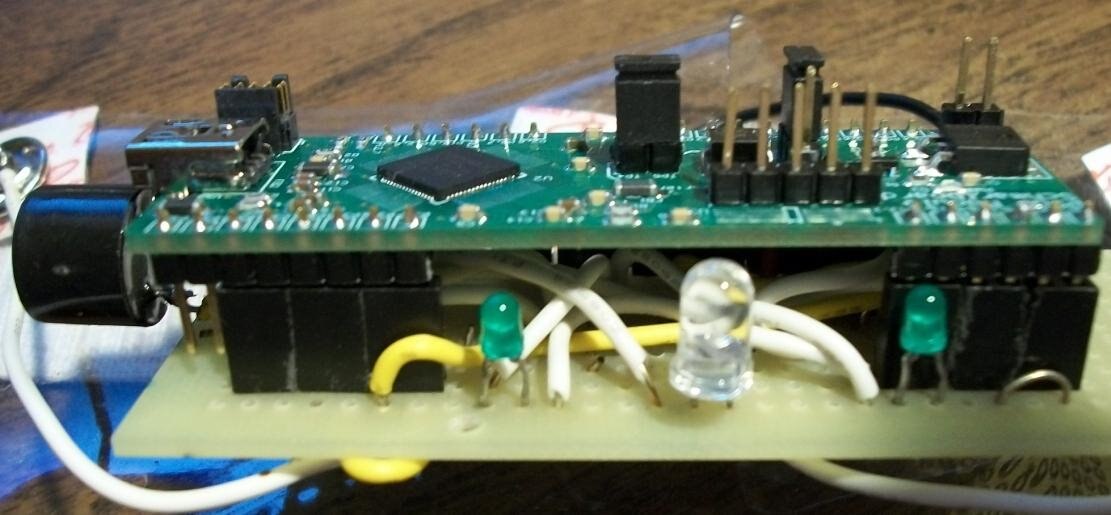
The two schematics are the same that I tried to implement into the Pioneer kit and I described in my previous update. The only difference is that now the bootloader block (that pink block on the upper right corner of the left side schematic) calls the bootloader file for schmartboard instead of the one for Pioneer kit. On these schematics I have highlighted with blue two sections: the passive resistors and capacitors part that is built in the front end module prototype board and the analog/digital part that is implemented in the PSoC5LP chip. The LEDs and buzzer on the right side are also implemented in the front end module. The picture below shows in more details the top and bottom side of the front end module.
<html><head><title>Jive SBS</title></head>
<body><font face="arial,helvetica,sans-serif">
<b>Error</b><br><font size="-1">
An general error occurred while processing your request.
</font></font></body></html>
All components are surface-mounted. The connectors are mounted so that they match the corresponding port connectors on the Schmartboard. That way, the prototype board plugs directly into the Schmartboard like this:
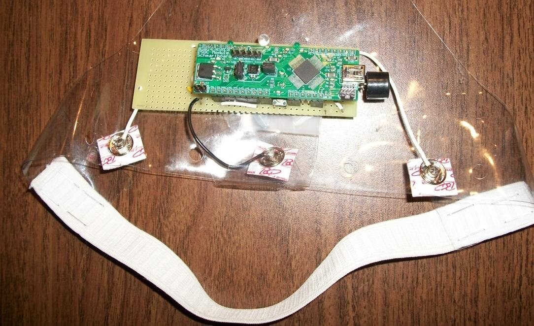
So after building this system I mounted it on a headband and connected the electrodes like this:
Then I placed it on my forehead and tested it , but… to my surprise it did not work 
Why didn't it work? I asked myself this question over and over, and the only thing I could do next was to troubleshoot this system to find out. The first test was to emulate the functionality on the lab test bench. To do this I applied 3.3V through a 100kOhm resistor to each one of the electrodes at a time (which should have similar effect as moving my eyes left/right but with much higher signal magnitude), like this:
As you can see, the brainwaves appliance controller functions on the test bench and it is able to turn the infrared receiver and light bulb on and off. But why doesn't work with bio-signals?
To answer this, I started to probe the electric signals along the amplifier path. For a stimulus, I used a sinusoidal waveform generator with a resistor divider attenuator and capacitive coupling into the electrode inputs. For this setting I first measured the attenuation factor as seen in this plot:
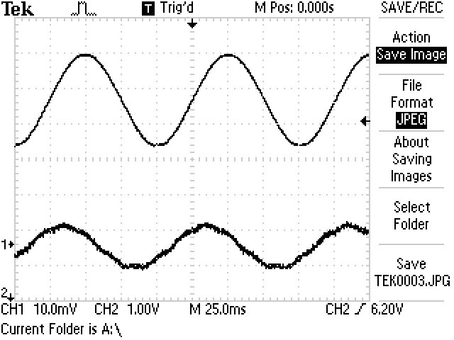
The generator output (ch2) had about 2.6V pk-pk signal and the attenuated signal had about 10mV pk-pk. So my resistor divider had an attenuation factor of about 3.85*10^(-3). This means that if I want to apply a signal similar to the electric levels of bio-signals generated by eye movement, which are in the order of 20-50uV, I need to set the generator amplitude to about 10mV (which has a value that I can measure with the oscilloscope). So I applied 10mV and I probed with the oscilloscope the output of opamp 3 in the schematic below, but the only thing I saw was noise; I couldn’t distinguish any sinusoidal signal. Then I measured the noise at the opamp 3 output without any signal applied at the input, and I saw significant high level of noise as I am showing in this plot:
<html><head><title>Jive SBS</title></head>
<body><font face="arial,helvetica,sans-serif">
<b>Error</b><br><font size="-1">
An general error occurred while processing your request.
</font></font></body></html>
As a first-order approximation, about 50mV pk-pk is random noise and about 500mV spikes may be deterministic noise. This random noise is quite high considering the amplifier has a gain of 50 and a 3dB bandwidth of about 1kHz, so it may be possible that the bio-signal voltage levels are so low that they get “lost” in noise. As a next step, I looked at the noise specs of the INA121U instrumentation amplifier that I used in my previous version of the brainwaves appliance controller which used a PSOC4 for data processing. The input referred noise of INA121U is specified as 20nV/sqrt(Hz) at f=1kHz. That circuit worked fine with bio-signals generated by eye movement (as I showed in a few of my Smarter Life Challenge updates ), so my next step was to check the specifications for the opamps inside the PSoC5LP. Here are the plots of input-referred noise voltage as function of frequency for INA121U and for PSOC5LP opamp (screenshots from the datasheets):
INA121U:
<html><head><title>Jive SBS</title></head>
<body><font face="arial,helvetica,sans-serif">
<b>Error</b><br><font size="-1">
An general error occurred while processing your request.
</font></font></body></html>
PSOC5LP Opamp:
<html><head><title>Jive SBS</title></head>
<body><font face="arial,helvetica,sans-serif">
<b>Error</b><br><font size="-1">
An general error occurred while processing your request.
</font></font></body></html>
Looking at these plots I noticed two main differences: random noise floor is lower for INA121U, 20nV/sqrt(Hz) compared to 45nV/sqrt(Hz) for PSOC5LP opamp. But the big difference is actually coming from the 1/f corner: INA121U has the 1/f corner at 20Hz while PSoC5LP has the 1/f corner at 20kHz. This is a huge difference considering that the brainwaves appliance controller operates at about DC to 100Hz bandwidth, where the 1/f noise dominates compared to random noise floor. Looking at these two plots, at 10Hz PSoC5LP has 1000nV/sqrt(Hz) while the INA121U has only 30nV/sqrt(Hz). This difference explains why INA121U was able to measure the bio-signals generated by my eye movements and PSoC5LP amplifier produced only noise.
So what should I do now? I don’t know yet. I am continuously thinking about a solution. One direction would be to keep a front end discrete amplifier but much simpler than what I used in PSoC4 Smarter Life Challenge project and implement the rest of analog functionality using PSoC5LP internal opamps. I need to think more about this.
This is where I am now with my brainwaves appliance controller system; I will continue to work on it and I will come back with a new update as soon as I have some results to share.
-

johnbeetem
-
Cancel
-
Vote Up
0
Vote Down
-
-
Sign in to reply
-
More
-
Cancel
Comment-

johnbeetem
-
Cancel
-
Vote Up
0
Vote Down
-
-
Sign in to reply
-
More
-
Cancel
Children