element14 Community
element14 Community
    Register Log In
  • Site
  • Search
  • Log In Register
  • About Us
  • Community Hub
    Community Hub
    • What's New on element14
    • Feedback and Support
    • Benefits of Membership
    • Personal Blogs
    • Members Area
    • Achievement Levels
  • Learn
    Learn
    • Ask an Expert
    • eBooks
    • element14 presents
    • Learning Center
    • Tech Spotlight
    • STEM Academy
    • Webinars, Training and Events
    • Learning Groups
  • Technologies
    Technologies
    • 3D Printing
    • FPGA
    • Industrial Automation
    • Internet of Things
    • Power & Energy
    • Sensors
    • Technology Groups
  • Challenges & Projects
    Challenges & Projects
    • Design Challenges
    • element14 presents Projects
    • Project14
    • Arduino Projects
    • Raspberry Pi Projects
    • Project Groups
  • Products
    Products
    • Arduino
    • Avnet Boards Community
    • Dev Tools
    • Manufacturers
    • Multicomp Pro
    • Product Groups
    • Raspberry Pi
    • RoadTests & Reviews
  • Store
    Store
    • Visit Your Store
    • Choose another store...
      • Europe
      •  Austria (German)
      •  Belgium (Dutch, French)
      •  Bulgaria (Bulgarian)
      •  Czech Republic (Czech)
      •  Denmark (Danish)
      •  Estonia (Estonian)
      •  Finland (Finnish)
      •  France (French)
      •  Germany (German)
      •  Hungary (Hungarian)
      •  Ireland
      •  Israel
      •  Italy (Italian)
      •  Latvia (Latvian)
      •  
      •  Lithuania (Lithuanian)
      •  Netherlands (Dutch)
      •  Norway (Norwegian)
      •  Poland (Polish)
      •  Portugal (Portuguese)
      •  Romania (Romanian)
      •  Russia (Russian)
      •  Slovakia (Slovak)
      •  Slovenia (Slovenian)
      •  Spain (Spanish)
      •  Sweden (Swedish)
      •  Switzerland(German, French)
      •  Turkey (Turkish)
      •  United Kingdom
      • Asia Pacific
      •  Australia
      •  China
      •  Hong Kong
      •  India
      •  Korea (Korean)
      •  Malaysia
      •  New Zealand
      •  Philippines
      •  Singapore
      •  Taiwan
      •  Thailand (Thai)
      • Americas
      •  Brazil (Portuguese)
      •  Canada
      •  Mexico (Spanish)
      •  United States
      Can't find the country/region you're looking for? Visit our export site or find a local distributor.
  • Translate
  • Profile
  • Settings
Smarter Life
  • Challenges & Projects
  • Design Challenges
  • Smarter Life
  • More
  • Cancel
Smarter Life
Blog I’ve fixed my PoC5LP  Brainwaves Appliance Controller
  • Blog
  • Forum
  • Documents
  • Files
  • Events
  • Mentions
  • Sub-Groups
  • Tags
  • More
  • Cancel
  • New
  • Share
  • More
  • Cancel
Group Actions
  • Group RSS
  • More
  • Cancel
Engagement
  • Author Author: ciorga
  • Date Created: 28 Apr 2014 5:37 AM Date Created
  • Views 1413 views
  • Likes 3 likes
  • Comments 5 comments
  • brainwave_controller
  • smarter_life
Related
Recommended

I’ve fixed my PoC5LP  Brainwaves Appliance Controller

ciorga
ciorga
28 Apr 2014

I have found a way to solve the technical issues described in my previous blog  and now my brainwaves appliance controller implemented in PSoC5LP works.   To get around the noise problem I implemented the front-end amplifier using a INA121 instrumentation amplifier as I am showing in the schematic below.  I set the gain to about 25 through a 2kOhm resistor made of R4 and R5 in series.  The center node is at the common mode voltage of the two inputs.  This common voltage node is buffered by one half of TI’s OPA2314  operational amplifier and then amplified by the second half to drive the RLD electrode and thus to create a negative feedback loop that prevents the common mode to drift outside the INA121 specifications.


Fullscreen contentimage_46283.html Download
<html><head><title>Jive SBS</title></head>
<body><font face="arial,helvetica,sans-serif">
<b>Error</b><br><font size="-1">
An general error occurred while processing your request.
</font></font></body></html>


The ports OUT, VREF, REF1, and REF2 are connected to I/O pins of PSOC5LP chip.  The program implemented in the PSoC5LP MCU controls the infrared LED D3, the buzzer, and the two “left move” and “right move” indicator LEDs D1 and D2.


The physical implementation used the PSoC5LP of the Schmartboard evaluation board that I described in my previous blog post.  The additional components shown in the schematic above are mounted on a soldered breadboard and connected to the Schmartboard  I/O connector.  The entire system is then mounted on a headband as shown in the picture below.


image


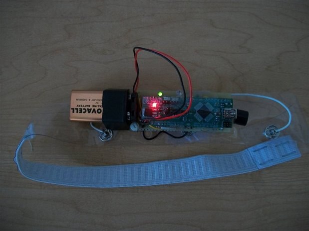
To power it up I used a 9V battery, but for the final design I am planning to use a 3V supply from a small battery CR2032 the type that is used on computers motherboards.  I will transition to that battery type after I finalize the algorithm in PSoC5LP and I implement all possible power savings techniques.


So now that it works what are the next steps?  Well, the first step that I already started to work on is to make this system able to learn any infrared remote control code.  This will allow users to “program” this brainwaves appliance controller to specific tasks mapped to various sequences of eye movements.  For example, turning a TV On and Off can be mapped to moving the eyes in a certain sequence like left -> right -> left.  Similarly, changing the channel up or down can be mapped to an eye movement sequence like left -> right -> right.  In my previous experiments when I turned my TV on and changed channels using the brainwaves appliance controller I preloaded the infrared remote codes into the program loaded in the PSoC chip.  To do this I measured the electric signal driving the infrared LED of the remote control with an oscilloscope and I “manually” decoded it.  While this procedure worked for my specific remote control that time, now I want to make the brainwave appliance controller able to learn any command from any infrared remote directly, without the need to reprogram the PSOC chip. 


This  is not an easy task; after starting to get familiar with infrared remotes and transmission codes I found out that there are multiple protocols of data encoding and even worse, multiple carrier frequencies.  The most common carrier frequencies are between 33kHz and 60kHz:  30kHz, 33kHz, 36kHz, 38kHz, 40kHz, and 56kHz.  Infrared receiver chips are of two types: the most common type receives and decodes the signal, however, one receiver chip is “tuned” for only one carrier frequency.  If I want to use this type of receiver I then need to have one receiver for each possible carrier frequency, which will increase significantly the cost and size.  The second type of infrared receiver is a “raw” signal receiver that outputs a digital signal representing the pulse-modulated carrier frequency.  To further clarify how they work I built a simple experiment using both types of receivers: a TSMP6000  that shows the raw signal and allows measurement of carrier frequency (response 20kHz to 60kHz) and a TSOP38238  that is tuned on a single carrier frequency and outputs the demodulated signal. I have mounted these two receivers on a prototype board as shown in the figure below:


image


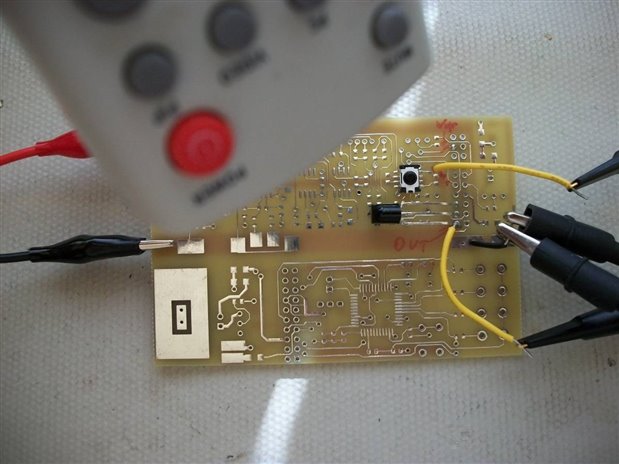
I then powered up the board from a 3V supply, I pressed the buttons on a remote control, and I measured the waveforms with an oscilloscope.  The figure below shows two signals: the lower waveform represents the output of TSOP38238, which is the demodulated signal, and the upper waveform represents the output of TSMP6000, which is the same signal but with the carrier frequency.


image

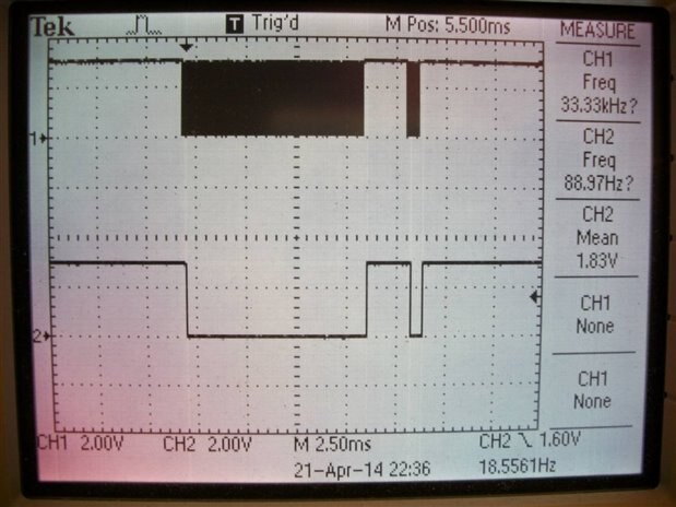
The carrier signal can be easier to see on a magnified time scale, as shown in the plot below.


Fullscreen contentimage_46287.html Download
<html><head><title>Jive SBS</title></head>
<body><font face="arial,helvetica,sans-serif">
<b>Error</b><br><font size="-1">
An general error occurred while processing your request.
</font></font></body></html>


The measured frequency is 39.58kHz.


So how am I going to approach the infrared code learning task?   I will need to measure the carrier frequency and to demodulate the pulse inside the PSoC5LP chip.  After that I will need to identify the transmission protocol.  There are various protocols but all of them have in common three sections:  starting code, address code, and data code.  Timing between these parts varies for each protocol, and logic “1” and “0” encoding also varies with each protocol. So I have to build an algorithm that measures the carrier frequency, determines the transmission protocol, measures the timing between all sections of the transmitted code, for each section decodes the sequence of “1” and “0”, and then saves the information in the EEPROM memory of the PSoC5LP.


This is where I am now with the brainwaves appliance controller project.  I will continue to work on this infrared code learning task and I will keep you updated with more results as I get more work done.


Best Wishes,

Cosmin

  • Sign in to reply
  • ciorga
    ciorga over 7 years ago

    Fig4 in datasheet shows the connections to a processor (Arduino uno in your application).  The Arduino code needs to access the TGAM registers through a UART serial interface and then prepare and send the data to a computer through another UART interface and in a format that can be processed by audacity application.  There are a few issues that need to be clarified: how fast the data needs to be transferred to the computer (this depends on your specific application; see page 3 of datasheet for baud rates - for raw eeg you will need 57.6k).  There is still other information needed like for example how to access the internal registers and read the measured data in TGAM chip - there should be probably a user manual with this information (register map and access protocol). Additionally writing the code needs to be done in parallel with testing the code on a prototype system (mindflex gear + Arduino board + USB interface to computer + Audacity running on the computer).  Just the Arduino code written "abstractly" may not work from the first time when tested on prototype system, so additional iterations will probably be needed. This becomes quite a complex project that involves significant time and effort.  I can try to help you with answering specific questions but because I am involved in multiple other projects at this time I don't think I will have the time needed to develop this entire system.

    • Cancel
    • Vote Up 0 Vote Down
    • Sign in to reply
    • More
    • Cancel
  • ciorga
    ciorga over 7 years ago

    Do you have the datasheet of Mindflex EEG?

    • Cancel
    • Vote Up 0 Vote Down
    • Sign in to reply
    • More
    • Cancel
  • ciorga
    ciorga over 7 years ago

    I think I need more details.  I can probably build a project fro the info that you sent me but it may use a different approach than what you at planning to use and maybe different/additional components.  I think I need more detailed info (specifications) of what you want to build and the specifications (and datasheets of the components/boards that you plan to use)  of what you need me to help with.

    Regards,

    Cosmin

    • Cancel
    • Vote Up 0 Vote Down
    • Sign in to reply
    • More
    • Cancel
  • ciorga
    ciorga over 7 years ago

    Sure, send me details and I can write the code for your project.

    Regards,

    Cosmin

    • Cancel
    • Vote Up 0 Vote Down
    • Sign in to reply
    • More
    • Cancel
  • DAB
    DAB over 11 years ago

    Great update Cosmin.


    I am very glad that you are continuing to work on your design and providing updates.


    DAB

    • Cancel
    • Vote Up 0 Vote Down
    • Sign in to reply
    • More
    • Cancel
element14 Community

element14 is the first online community specifically for engineers. Connect with your peers and get expert answers to your questions.

  • Members
  • Learn
  • Technologies
  • Challenges & Projects
  • Products
  • Store
  • About Us
  • Feedback & Support
  • FAQs
  • Terms of Use
  • Privacy Policy
  • Legal and Copyright Notices
  • Sitemap
  • Cookies

An Avnet Company © 2025 Premier Farnell Limited. All Rights Reserved.

Premier Farnell Ltd, registered in England and Wales (no 00876412), registered office: Farnell House, Forge Lane, Leeds LS12 2NE.

ICP 备案号 10220084.

Follow element14

  • X
  • Facebook
  • linkedin
  • YouTube