I have found a way to solve the technical issues described in my previous blog and now my brainwaves appliance controller implemented in PSoC5LP works. To get around the noise problem I implemented the front-end amplifier using a INA121 instrumentation amplifier as I am showing in the schematic below. I set the gain to about 25 through a 2kOhm resistor made of R4 and R5 in series. The center node is at the common mode voltage of the two inputs. This common voltage node is buffered by one half of TI’s OPA2314 operational amplifier and then amplified by the second half to drive the RLD electrode and thus to create a negative feedback loop that prevents the common mode to drift outside the INA121 specifications.
<html><head><title>Jive SBS</title></head>
<body><font face="arial,helvetica,sans-serif">
<b>Error</b><br><font size="-1">
An general error occurred while processing your request.
</font></font></body></html>
The ports OUT, VREF, REF1, and REF2 are connected to I/O pins of PSOC5LP chip. The program implemented in the PSoC5LP MCU controls the infrared LED D3, the buzzer, and the two “left move” and “right move” indicator LEDs D1 and D2.
The physical implementation used the PSoC5LP of the Schmartboard evaluation board that I described in my previous blog post. The additional components shown in the schematic above are mounted on a soldered breadboard and connected to the Schmartboard I/O connector. The entire system is then mounted on a headband as shown in the picture below.
To power it up I used a 9V battery, but for the final design I am planning to use a 3V supply from a small battery CR2032 the type that is used on computers motherboards. I will transition to that battery type after I finalize the algorithm in PSoC5LP and I implement all possible power savings techniques.
So now that it works what are the next steps? Well, the first step that I already started to work on is to make this system able to learn any infrared remote control code. This will allow users to “program” this brainwaves appliance controller to specific tasks mapped to various sequences of eye movements. For example, turning a TV On and Off can be mapped to moving the eyes in a certain sequence like left -> right -> left. Similarly, changing the channel up or down can be mapped to an eye movement sequence like left -> right -> right. In my previous experiments when I turned my TV on and changed channels using the brainwaves appliance controller I preloaded the infrared remote codes into the program loaded in the PSoC chip. To do this I measured the electric signal driving the infrared LED of the remote control with an oscilloscope and I “manually” decoded it. While this procedure worked for my specific remote control that time, now I want to make the brainwave appliance controller able to learn any command from any infrared remote directly, without the need to reprogram the PSOC chip.
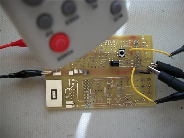
This is not an easy task; after starting to get familiar with infrared remotes and transmission codes I found out that there are multiple protocols of data encoding and even worse, multiple carrier frequencies. The most common carrier frequencies are between 33kHz and 60kHz: 30kHz, 33kHz, 36kHz, 38kHz, 40kHz, and 56kHz. Infrared receiver chips are of two types: the most common type receives and decodes the signal, however, one receiver chip is “tuned” for only one carrier frequency. If I want to use this type of receiver I then need to have one receiver for each possible carrier frequency, which will increase significantly the cost and size. The second type of infrared receiver is a “raw” signal receiver that outputs a digital signal representing the pulse-modulated carrier frequency. To further clarify how they work I built a simple experiment using both types of receivers: a TSMP6000 that shows the raw signal and allows measurement of carrier frequency (response 20kHz to 60kHz) and a TSOP38238 that is tuned on a single carrier frequency and outputs the demodulated signal. I have mounted these two receivers on a prototype board as shown in the figure below:
I then powered up the board from a 3V supply, I pressed the buttons on a remote control, and I measured the waveforms with an oscilloscope. The figure below shows two signals: the lower waveform represents the output of TSOP38238, which is the demodulated signal, and the upper waveform represents the output of TSMP6000, which is the same signal but with the carrier frequency.
The carrier signal can be easier to see on a magnified time scale, as shown in the plot below.
<html><head><title>Jive SBS</title></head>
<body><font face="arial,helvetica,sans-serif">
<b>Error</b><br><font size="-1">
An general error occurred while processing your request.
</font></font></body></html>
The measured frequency is 39.58kHz.
So how am I going to approach the infrared code learning task? I will need to measure the carrier frequency and to demodulate the pulse inside the PSoC5LP chip. After that I will need to identify the transmission protocol. There are various protocols but all of them have in common three sections: starting code, address code, and data code. Timing between these parts varies for each protocol, and logic “1” and “0” encoding also varies with each protocol. So I have to build an algorithm that measures the carrier frequency, determines the transmission protocol, measures the timing between all sections of the transmitted code, for each section decodes the sequence of “1” and “0”, and then saves the information in the EEPROM memory of the PSoC5LP.
This is where I am now with the brainwaves appliance controller project. I will continue to work on this infrared code learning task and I will keep you updated with more results as I get more work done.
Best Wishes,
Cosmin


-

ciorga
-
Cancel
-
Vote Up
0
Vote Down
-
-
Sign in to reply
-
More
-
Cancel
Comment-

ciorga
-
Cancel
-
Vote Up
0
Vote Down
-
-
Sign in to reply
-
More
-
Cancel
Children