


This was a “bumpy” weekend; it started quite good: I built an active Butterworth second order low pass filter using one of the opamps inside PsoC4. I put together all external components and configured the PsoC opamp to route the output off-chip so I could probe it with the oscilloscope. I then swept the input frequency (connected to a sinusoidal generator) and everything worked so good. The cut-off frequency was just as calculated, around 50Hz.
Then the problems started: I realized that I need a window comparator (this was based on the measured waveforms that I showed in my previous update). So I configured it using the two comparators inside PsoC4, but when I tried to build the project I’ve got a resource availability error. So then I figured out that I cannot use two comparators and an opamp; only either two opamps, two comparators, or one opamp and one comparator.
Next I moved the filter off-chip and I built a window comparator using the two opamps/comparators inside PsoC4. Then I realized that I could eliminate the low-pass filter for now if I use a debouncer block available in PsoC4. I setup a 10Hz clock to the debouncer and here is the schematic:
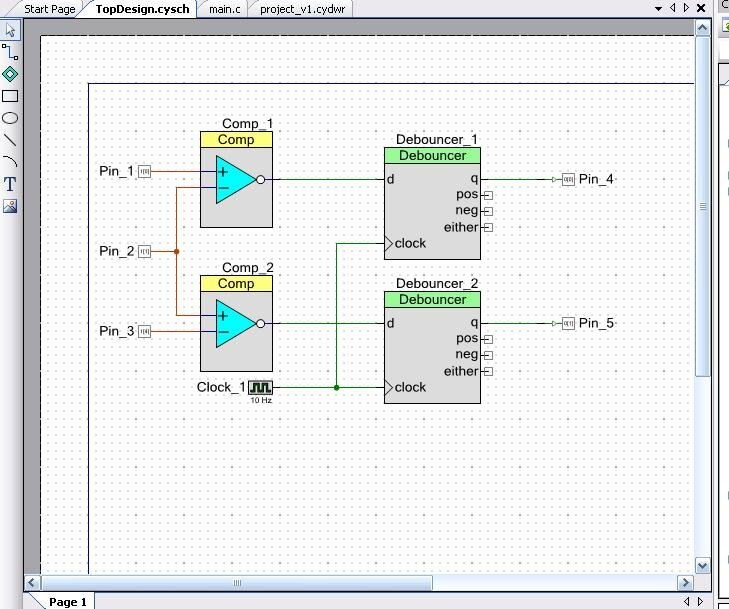
I then routed the two outputs of the window comparator off-chip to two LEDs (in series with two 2.2k resistors).
So I could built this project and program the PsoC on the Pioneer kit. Then while running various experiments and re-building the project, at some point my circuit stopped working. One LED never turned ON.
So I started to troubleshoot this issue and after more than one hour I figured out what was happening: PsoC Creator program was “optimizing” my project by removing one of the opamps/comparator. During the troubleshooting pricess I found useful the diagram shown under the “Analog” tab in the pin mapping frame:
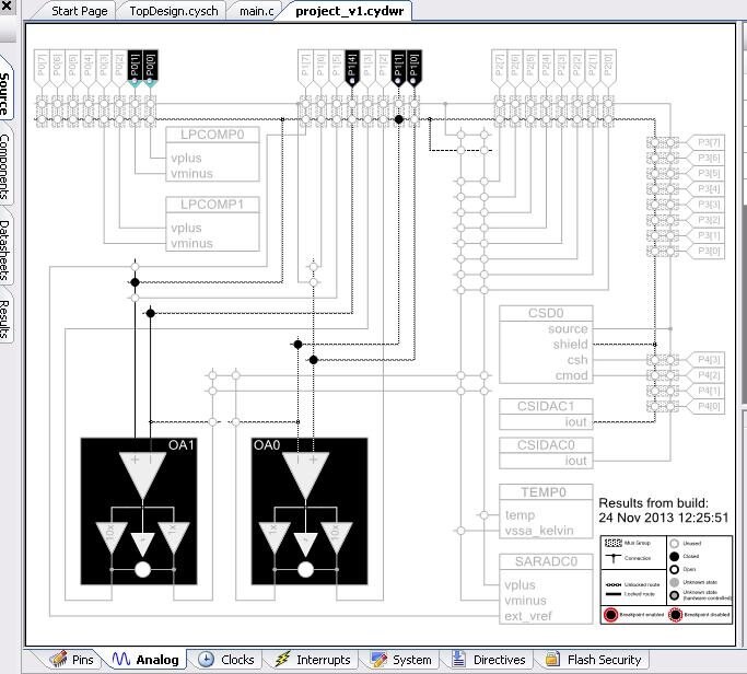
This one looks correct but the wrong one, which I did not screenshot, showed one opamp without one of the input connections and also was signaling a warning that one of the pins (that pin that I wanted routed to the opamap) is not connected. Further tracing this issue I found out that the optimizer removed one of my opamps.
So after about 1.5-2 hours of poking around I came up with a solution: the only think that worked was to start a new project from scratch. This fixed the problem and I’ve got both of my opamps in the built project.
If anyone knows a way to disable the PsoC Creator optimizer, I would greatly appreciate if he/she can share that technique with me.
Next, I put together the off-chip amplifier that I built before (and I showed the measured waveforms in my previous updates). The resulted “system” contains the electrodes placed on the forehead skin, the off-chip amplifier, the window comarator inside PsoC4 (on the Pioneer kit), the debouncers used here as low pass filters, and two off-chip LEDs (one yellow and one green).
When I then mounted this system on my head and turned it ON, the electrodes measured the electric signals associated to moving my eyes left and right, and these signals were then amplified and processed by the window comparator. The result could be then visualized by watching the two LEDs (I have placed them above each of my eyes – with some wires hanging there).
So each of the two LEDs lights up on one direction of eye movement: one LED lights up when I move the eyes towards left and the other LED lights up when I move the eyes towards right.
Here is a video that shows this experiment:
Don’t get scared by so many wires and boards hanging up from my forehead (they are various experimental circuits some active and some inactive hanging there) – the PCB board that I am designing will be quite small; enough small to make this project easy portable.
So this is my update for this weekend: so far I was able to measure the electric signals associated to eye movements and I was able to process them into a detectable form that I used in this experiment to light up the two LEDs.
That’s it for this weekend; I’ll post more updates as I get more work done.
Best Wishes,
Cosmin


