Table of contents
Abstract
My "Start a Movement" design challenge entry includes a connector tester. This blog covers a first look at the electronics and software involved in the connector tester.
Project
Intro
This installment of my Start A Movement design challenge project covers the connector tester electronics and software. The first video shows progress on the stepper motor control front because this challenge is fundamentally about the Analog Devices stepper motor controller. However an element14 design challenge needs some electronics design and that is the main subject of this blog.
Video - Motor Control Update
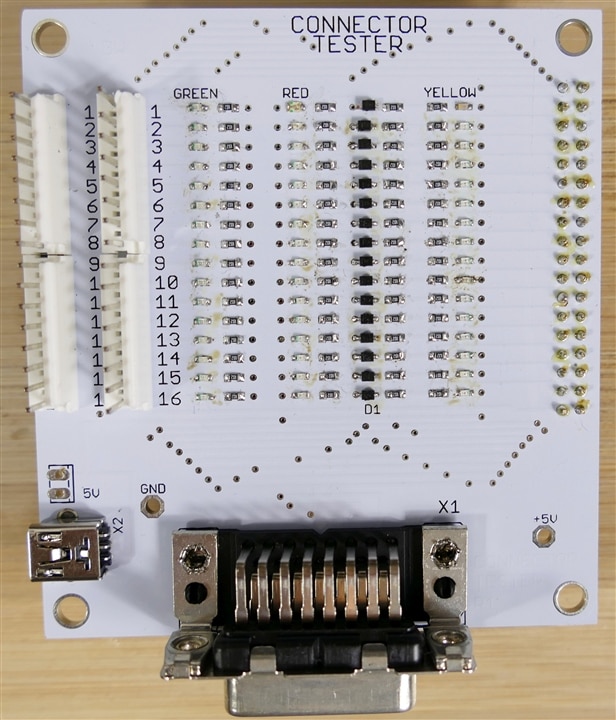
Image - Connector Tester Circuit Card Assembly

Video - First Connector Tester Hardware/Software Test
Video - Full Connector Tester Circuit and Software Demo
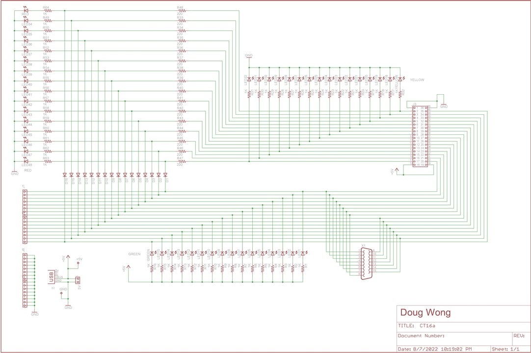
Connector Tester Schematic

Above is the schematic for the PCB in the demo. It allows open and short circuits to be tested with different connection schemes.
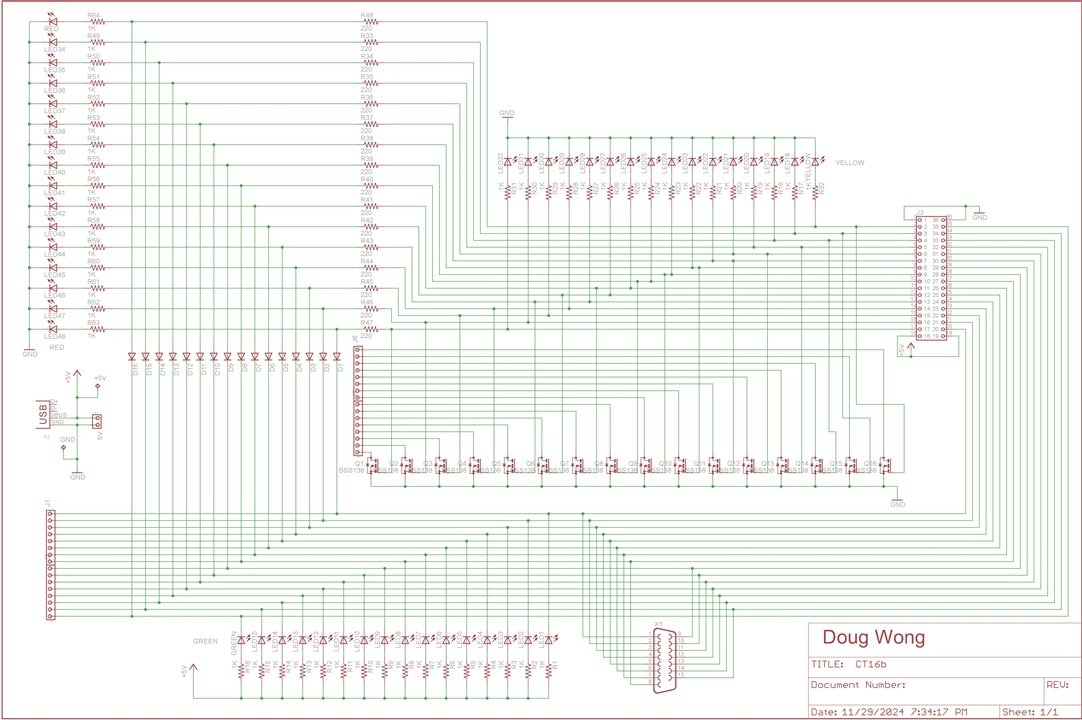
Below is another schematic that allows opens and shorts to be tested with everything connected - if anyone needs that functionality:

Mega Firmware
// Connector Tester Program
// Doug Wong
// 2024
// 16 pin connector and cable tester program for an Arduino Mega
//

 #include <Wire.h>
 #include <LiquidCrystal_I2C.h>
 LiquidCrystal_I2C lcd(0x27,  20, 4);

int pinI[16] = {53, 51, 49, 47, 45, 43, 41, 39, 37, 35, 33, 31, 29, 27, 25, 23};
int pinO[16] = {52, 50, 48, 46, 44, 42, 40, 38, 36, 34, 32, 30, 28, 26, 24, 22};

int cycles;
int faults;
int trigger, oldtrigger;
int triggerpin = 1;

void setup() {
  lcd.begin();
  lcd.clear();
  lcd.print("     element14");
  lcd.setCursor(0, 1);
  lcd.print("  Start A Movement");
  lcd.setCursor(0, 2);
  lcd.print("Cycles 0");
  lcd.setCursor(0, 3);
  lcd.print("Faults 0");

  pinMode(triggerpin, INPUT);	//configure trigger pin

  for (int i = 0; i < 16; i++) {	//configure digital pins
   pinMode(pinI[i], INPUT);
   pinMode(pinO[i], OUTPUT);
  }
  trigger = digitalRead (triggerpin);
  oldtrigger = trigger;
}

void loop() {
  trigger = digitalRead (triggerpin);
  if (trigger != oldtrigger){           //trigger pin has changed state
    oldtrigger = trigger;
    delay (100);
    if (trigger == 1){                  //trigger detected
      cycles++;
      for (int j = 0; j < 16; j++){     //enable 16 outputs
       digitalWrite (pinO[j], HIGH);
      }
      for (int n = 0; n < 16; n++){     //read 16 inputs to determine state of each
        if (digitalRead(pinI[n]) == 1){
          faults++;                     //if a fault is detected increment the fault counter
        }
      }
      delay(100);
      lcd.setCursor(7, 2);
      lcd.print(cycles);
      lcd.setCursor(7, 3);
      lcd.print(faults);
      delay(400);
      for (int k = 0; k < 16; k++){     //disable 16 output pins
        digitalWrite (pinO[k], LOW);
      }
    }
  }
}
Discussion
Soldering 48 LEDs and associated circuitry is a bit tedious, but visual indicators make for better video. The PCB works as intended although implementing the second schematic above might make a better production test system because it can perform more tests with fewer manual actions. So far the project is proceeding well, however the hard mechanical design elements are still to come and until they all work, there will be some tension and uncertainty. I will probably change the LCD info to indicate it is a connector tester.
Next Steps
- Design the Lead screw and linear bearing assembly and assemble it
- Design the connector brackets and print them
- Design the chuck assembly and build it
- Program and test the connector tester motor control
- Program and test the thread tapping motor control
Links
- Project Blog 1 - Unboxing
- Project Blog 2 - Connector Tester Electronics and Firmware
- Project Blog 3 - Linear Actuator
- Project Blog 4 - Rotary Actuator
- Project Blog 5 - Connector Tester Demo
- Project Blog 6 - Thread Tapping System
- Project Blog 7 - Project Summary and discussion
- Start a Movement Design Challenge page
- Analog Devices TMC5272 page
- TMCL-IDE page

