Table of contents
Abstract
It is required to design a mobile stage for XY movements in a metallurgical microscope. The initial proposal consists of a one axis stage controlled by the TMCL-IDE for displacement and the camera software for acquisition.
Project
Connector management for power and motor
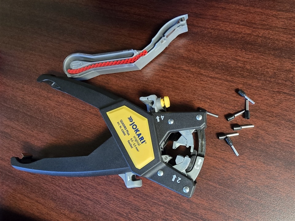
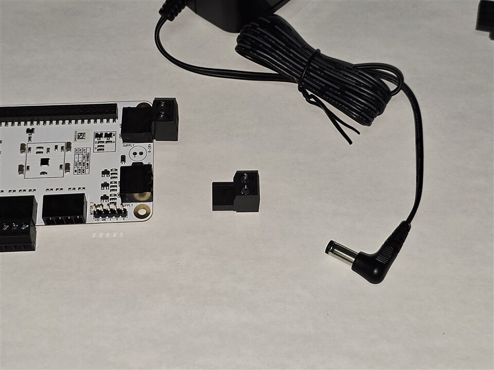
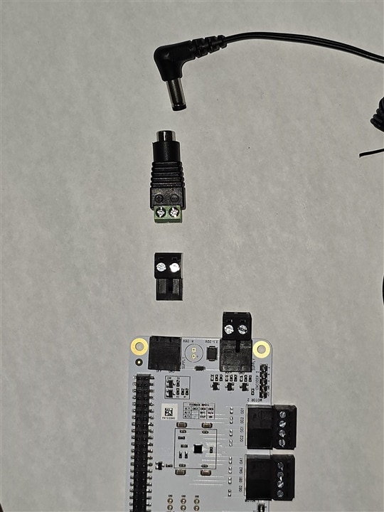
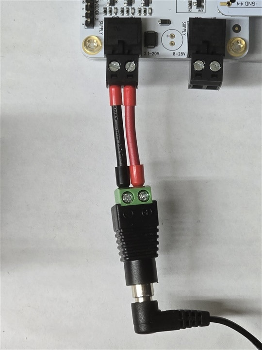
To increase the possibilities in the TMC5272 EVAL board I added a second stepper motor to test the interfaces. But before starting any test, a crimping tool set is used to prepare the wires for the manufacturer's connectors. The provided power source is 12V@1A, which means that both motors could not run at the same time, only decreasing the power consumption in the TMCL IDE. The crimp tool is used to prevent damage to the provided power supply connector. A CCTV connector is used with two wires as a bridge between the board connector and the power connector.
| {gallery}Supply Connector |
|---|
|
|
|
|
|
|
 |
The second motor is a SY20STH42-0804A from pololu, which features are compared with the provided motor below
| QSH4218-35-10-027 | SY20STH42-0804A | |
| Rated Voltage (V) | 5.3 | 4.2 |
| Rated Current (A) | 1.0 | 0.8 |
| Resistance Per Phase | 5.3 (20°C) | 5.4 (25°C) |
| Inductance Per Phase | 6.6 | 1.5 |
| Holding Torque | 27(N.cm) | 300 (g.cm) |
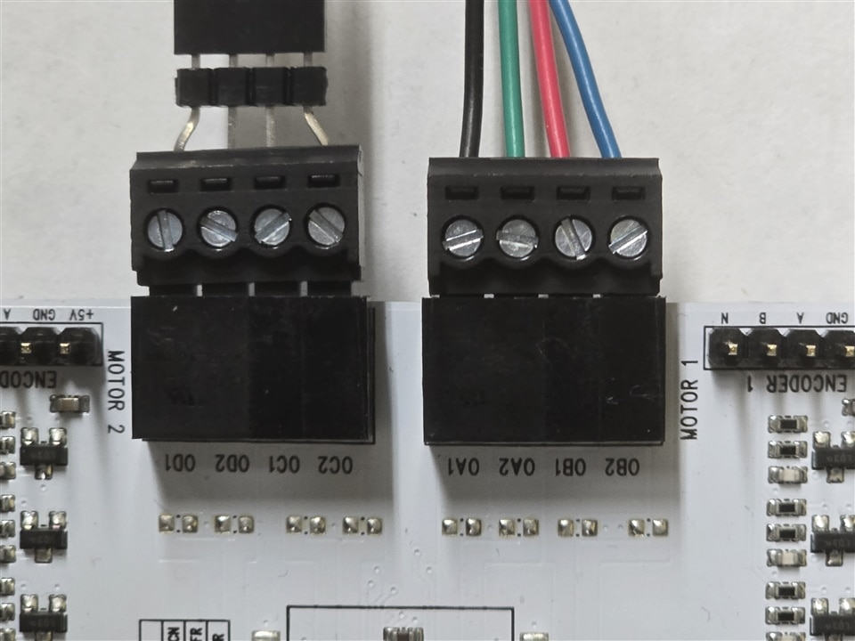
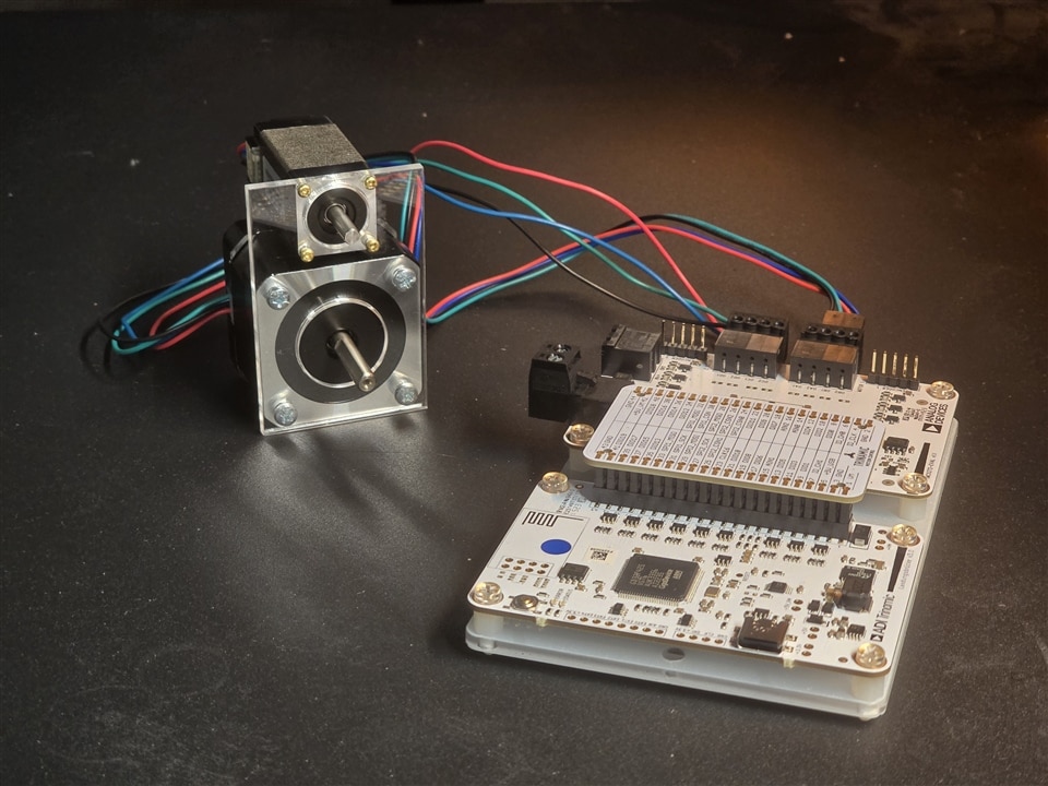
Some of the electrical features are similar, consequently, the second motor can be used in one of the channels of the board in addition to the capabilities of the power IC according to its datasheet. Since the motor I had was from a really old project and I did not want to damage its connector, a large header connector is molded to avoid inserting of more wires into the interface. Finally, the motor connections are shown below.
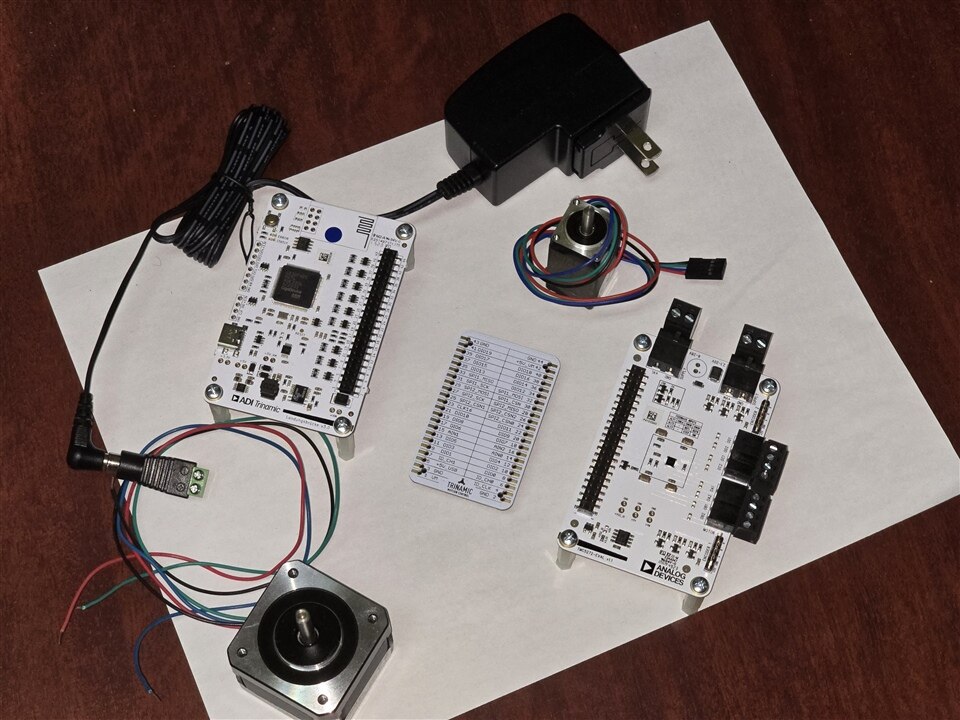
Here is the complete setup to be mounted, where some nylon dividers are mounted to protect the table from scratches caused by the soldered terminals.
Board Assembly
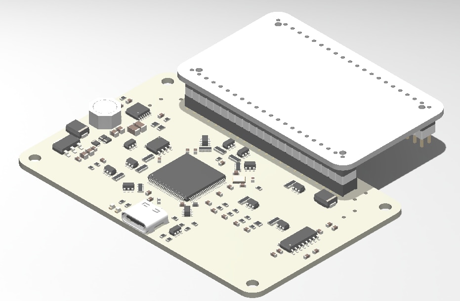
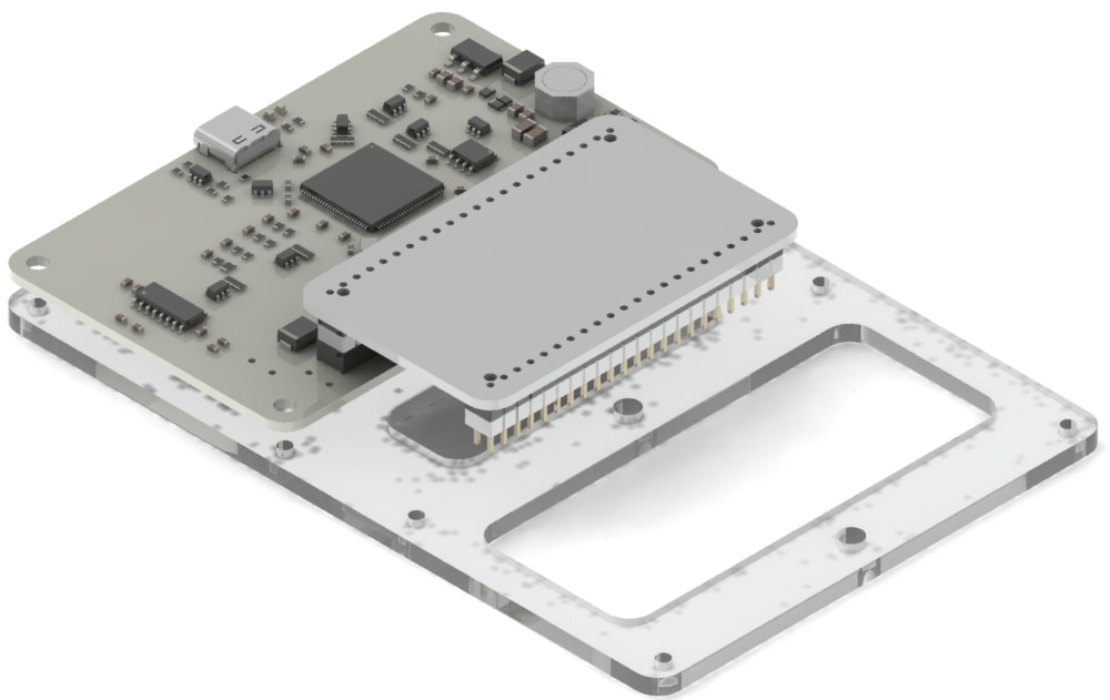
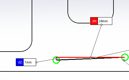
Once the connectors are prepared, the the main boards must be assembled to avoid possible short circuits or damage to the workbench. To do this, a support is designed to keep everything in its place. Although the AD website has 3D models to improve the visualization and design, I found that the latest version of the boards have an offset of about 1 mm, which means that using the manufacturer's model could bring a bad design directly. In consequence, I used a caliper to guarantee the dimensions.
| {gallery}Board Assembly |
|---|
|
|
 |
|
|
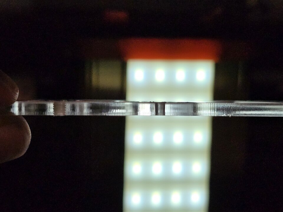
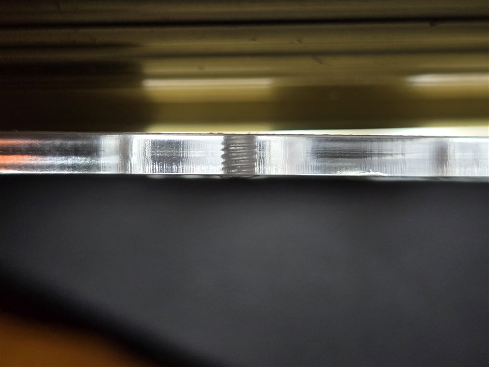
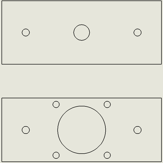
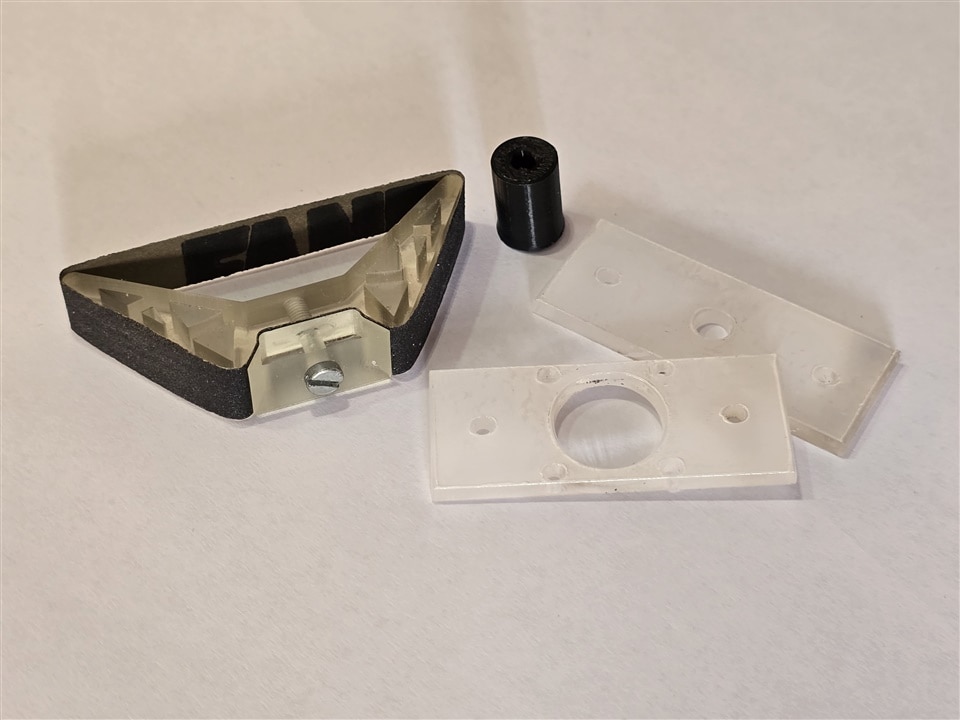
Some post-processing is required to complete the assembly. The designed pieces are usually manufactured by laser cut in acrylicSome post-processing is required to complete the assembly. The designed pieces are usually manufactured by laser cut in acrylic, consequently, some holes are reduced to create a thread for the screw mounting.
| {gallery}post-processing |
|---|
|
|
|
|
|
|
 |
Prototyping Stage
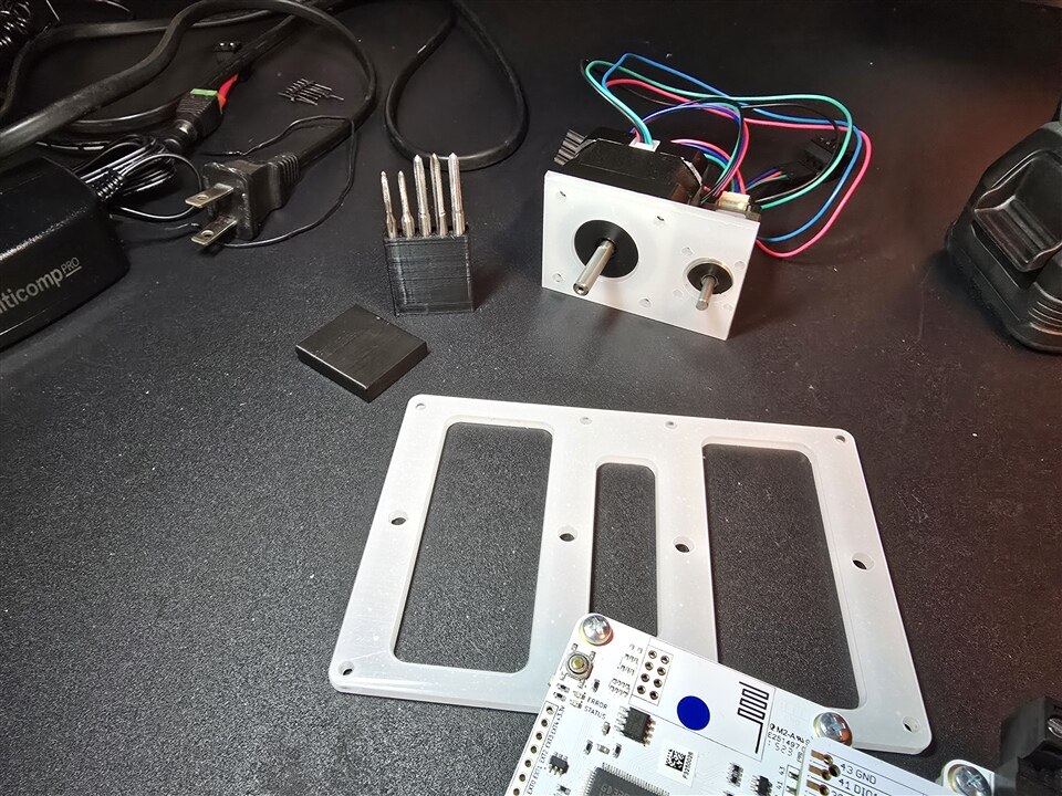
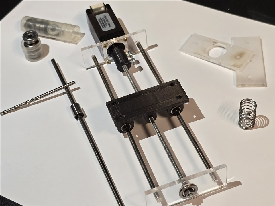
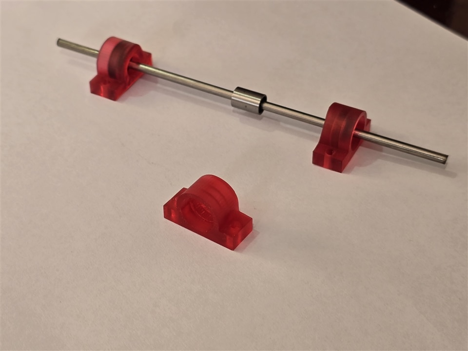
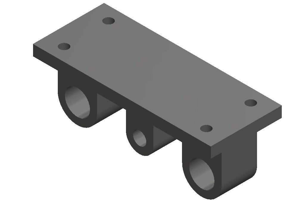
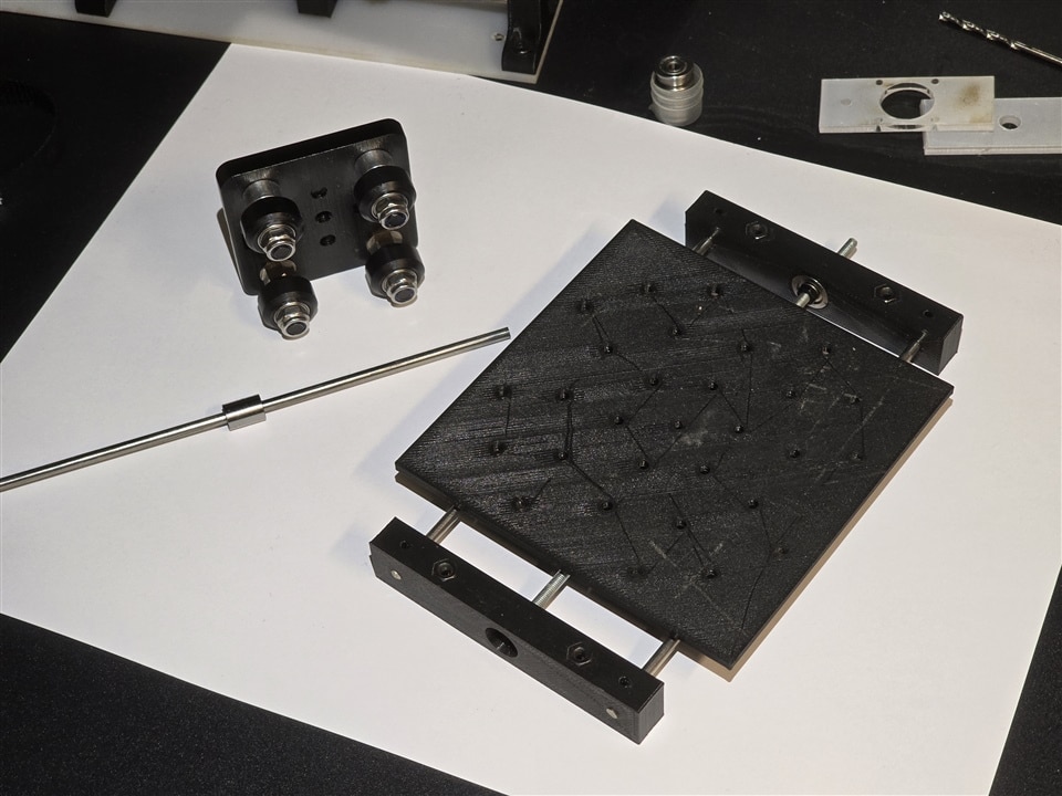
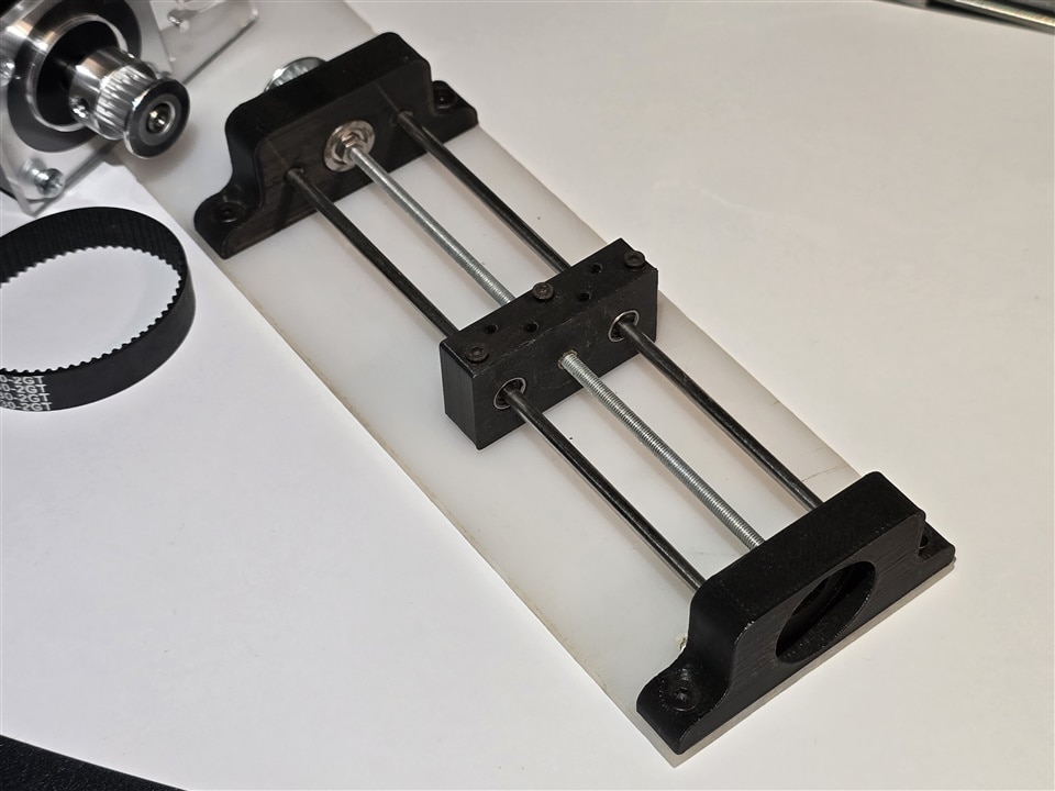
Laser cutting and 3D printing bring a wide range of prototyping options. Sometimes it is necessary to produce the parts for the project itself, but also to design and implement the necessary tools. I have a philosophy about these processes, all parts that I cannot obtain or are in the prototype stage should be cut/printed as there are no elements available compared to bearings, steel bars or screws and bolts.
| {gallery}Prototyping |
|---|
|
|
 |
|
|
|
|
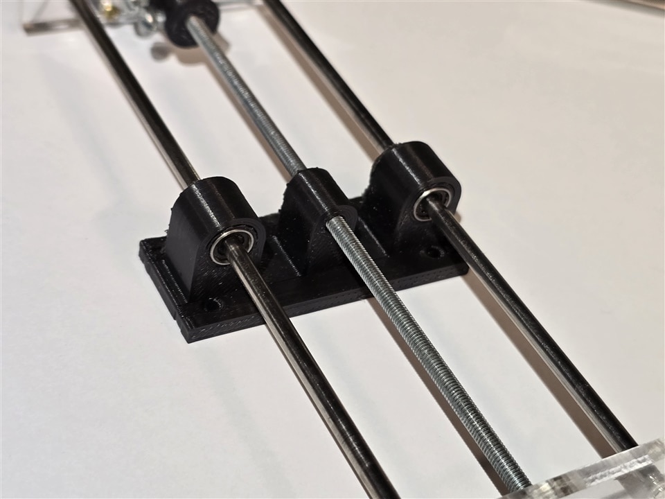
The nature of these processes allows the multiple proposals to be tested simultaneously in the entire system and select the best assembly to be used with the microscope and with the assistance of the TMCL-IDE, move the samples and throughout the field of view and acquire multiple images of the same sample. This example is shown in the next section.
| {gallery}Proposals |
|---|
|
|
 |
 |
 |
Testing proposals
The final stage of the challenge at the moment of writing this project is the visualization of the stage functionality. First, it is necessary to configure the current sensing in the motor board. To do this, both sensing configurations are shared, consequently, the motor 1 must be validated to be able to measure current correctly and confirm this configuration on the motor 2. This is required since the two motors have similar characteristics. For testing proposals, a current of 402 mA is configured for a 15kΩ reference resistor. This window is available clicking Device > Motor 1 > Current Settings
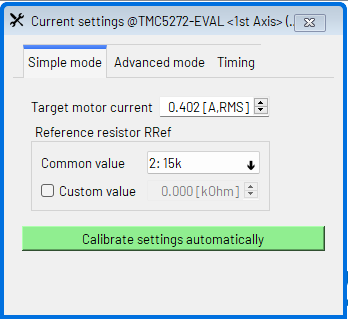
Once the configuration is correct, the video capture software, in coordination with the TMCL.IDE software, takes a complete shift of the image. Like many prototypes, the first proposal has misalignment errors that will be corrected in future releases of the project. On the other hand, the TMCL software can be configured to loop motion and capture a complete video reel for future analysis, or position the sample and capture individual frames.
Finally, a complete motion loop and video capture is shown below
Final Remarks
These test demostrate the feasibility of the stepping motor usage with the Trinamic platform for positioning and image capture with good enough quality. The prototype needs to be improved and a better material selection and manufacturing could reduce the error on the dynamic behavior of the X-axis stage. In addition to these, a second Y stage should be added for full-frame acquisition and a possible Z axis for the focal length compensation. I am grateful for the support of the project by the sponsor, who provided the motor controller and accessories. Finally, the project is continously improved and designed; I hope to use the encoder interfaces for closed-loop control soon.
References
https://www.pololu.com/product/2256
https://www.analog.com/en/lp/001/trinamic-support.html


