Table of contents
Abstract
Obtaining consistent AC voltage from the mains can be an expensive challenge. Can we solve this problem by outfitting a humble Variac with an ADI-Trinamic stepper motor to make it computer-controlled?
Project
Preface
What follows is an abridged version of the blog-forum-posts that I wrote for this challenge with a bit of extra progress added on. As it stands, my creation is still incomplete and thus this should be considered an incomplete project. I think that conceptually, it is fine but the execution is lacking. I must apologise to element14 and the sponsor, ADI Trinamic, for not being able to succeed as per my original proposal. I did at least give it my best shot, especially considering this project was hampered my a sudden temporary change in my health condition (losing central eyesight in one eye and losing the ability to walk or stand consistently) and from a triple-overlapping-RoadTest situation I was also facing.
The Problem and Concept
If you want a regulated DC power supply, you'd just grab a lab benchtop power supply or a plug-pack or perhaps even USB/USB-C PD and you'd be set. This is such a bread-and-butter requirement that we have a bread-and-butter solution to it.
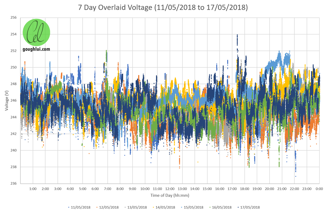
But if you want a regulated AC mains power supply, then that's a whole different kettle of fish. Your wall-socket nominal 115/230V is never quite exactly that, as loads inside the house and loads along your street can change the voltage at any time. This is simply down to how resistance in the transmission lines cause voltage drop as a function of current flow (ohms law). Aside from that, the distribution network often has tap changing transformers which can boost or buck by fixed ratios to try and bring the voltages within a band, as loads can change significantly throughout the day. For example, this is a graph I previously made of line voltage in my house across a 24 hour period:
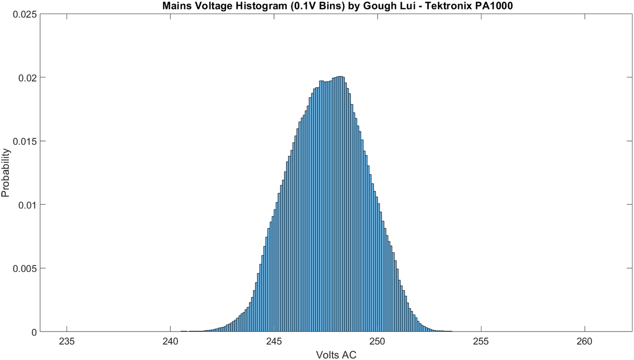
What is nominally 230V has quite a spread. But when testing certain sorts of appliances, the voltage has a direct bearing on energy consumption, so testing with a voltage that varies would be unfair. The IEC62301 standard that has to do with standby energy qualification, for example, sets stringent voltage requirements of +/-1% of nominal for accurate testing. As a result, ordinary mains power simply cannot do (and it likely can't for other reasons, including crest factor, but we can't do much about that in this challenge).
So, I called this project "AVR", short for "Automatic Voltage Regulator". The idea would be that by taking an autotransformer (e.g. a Variac) that allows for nearly-continuous output voltage control and connecting its mechanical input shaft in such a way that it can be computer controlled, we could "close the loop" on the system by using the readings from a power analyser (e.g. the Tektronix PA1000 I previously RoadTested) in order to counteract slow mains voltage movements (e.g. up to 2 adjustments per second) and keep the output voltage within a set band, hopefully rapid enough to take out most of the influence of grid voltage variation). This is not going to help if the mains voltage has a "step" change (e.g. due to tap changer operation) but the closer to the target voltage it is, the less likely such disturbances will push the output voltage out of band. In essence, we'd be trying to keep the voltage at the set-point all the time, similar to how someone would move around to keep a basketball balanced on their finger. It probably won't be able to guarantee a +/- 1% result, but it should mean that I can run my longer mains-powered appliance tests more comfortably with less "noise" in the readings.
For this, we need a Variac and thankfully, I have not one but two small ones. The one I will be using for this challenge is a Yamabishi Electric (Japanese) unit I wrote about here: A Shocking Variac Made a Little Less Shocking!
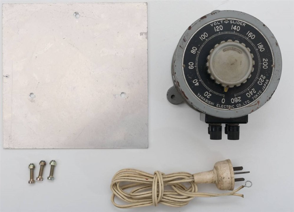
My plan would be to take the knob off of the unit, design a 3D printed coupling that might take a trio of M3 screws as grub screws on both sides to couple the shafts together, all with an adapter plate that keeps the alignment of the motor and Variac body constant. Then, using the provided driver and evaluation board, I'd figure out how to get it hooked up to the computer, under computer control (USB would be fine) whereby a script could then poll my PA1000 power analyser and set appropriate adjustments on the Variac, making decisions at every step as to whether to move it or not (as the carbon brush is something that will wear down quickly if excessive unnecessary adjustments are made).
You might be thinking "Well, hold on a minute. Don't those newfangled UPSes have AVRs in them?" and you'd be right. Many line-interactive UPSes advertise the presence of AVR functionality. However, their form of AVR is made with discrete windings on a transformer, thus allowing you to "boost" or "buck" the input by a fixed percentage increment, usually something between 5-10%, causing a massive jump every time it happens. For precision AC applications, this is not ideal.
Another thought may be "Why not just use a DC to AC true sine-wave inverter as a source? They're stable, right?" and this is something I'm already doing. However, what they don't tell you is that the inverters have some higher frequency harmonic content and insufficient regulation to deal with high crest-factor loads which leads to noticeable load-modulation of the voltage. Another issue I'm also finding is that the voltages from such inverters also jump, due to temperature changes within the board and compensation for that, which are a pain whenever the inverter is not on a constant load (as every heat-up and cool-down cycle, especially with thermostatic fan) results in a voltage jump. They also seem to have an offset from the factory (230V nominal is often measured at 233V or 235V) which necessitates trimming and their limited reactive power capabilities seem to cause my power analyser to give very inaccurate power-factor readings.
Getting nice, regulated, powerful AC is something that, ideally, you should be using a synthetic mains AC source (such as these behemoths from GWInstek or Keysight) for. My pockets aren't quite so deep though ... so I'm going to try and be clever.
Unboxing
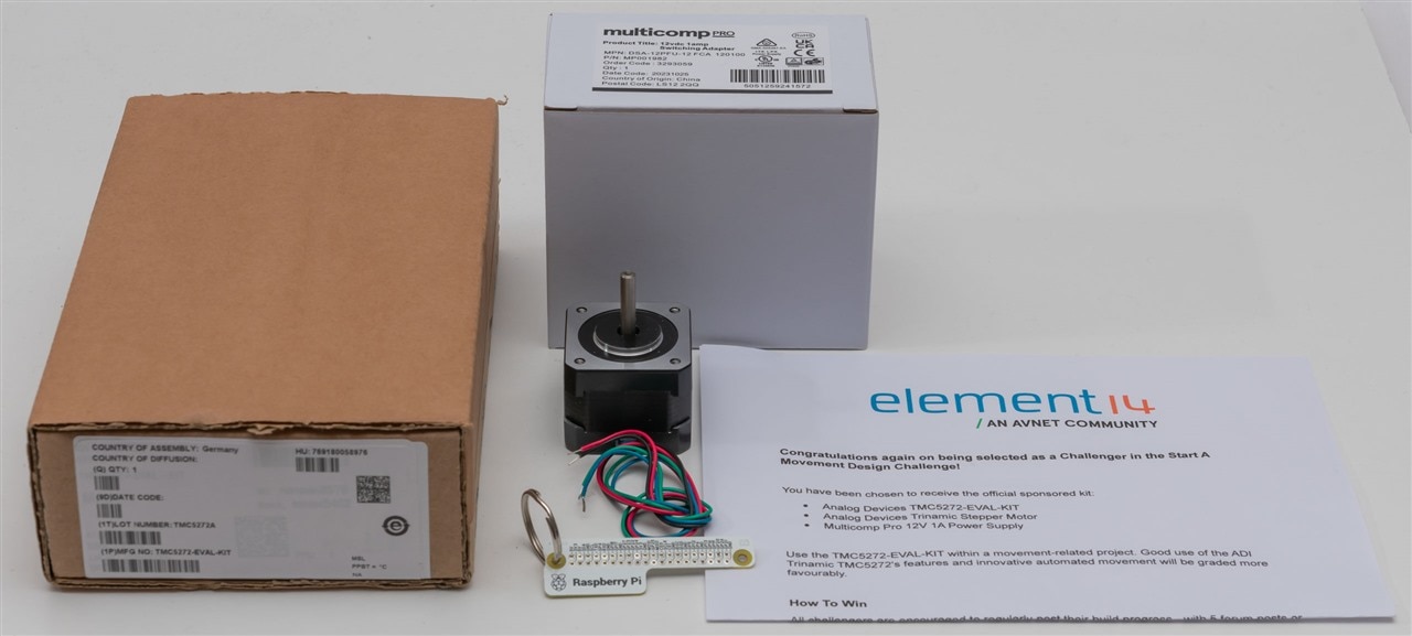
The main stars of the show are the electronics from ADI Trinamic on the left, the power supply (top) and the stepper motor (middle).
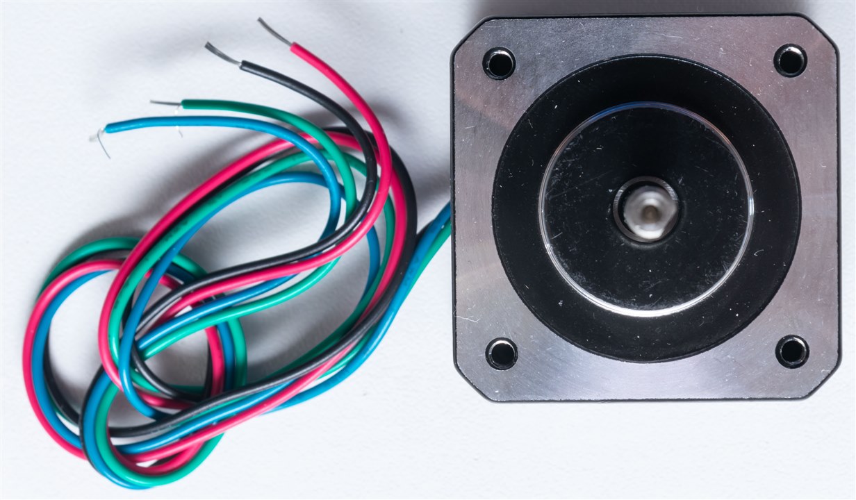
The stepper motor looks to be a NEMA-style unit, similar to what you might find on consumer hobby-level 3D printers (at least, visually).
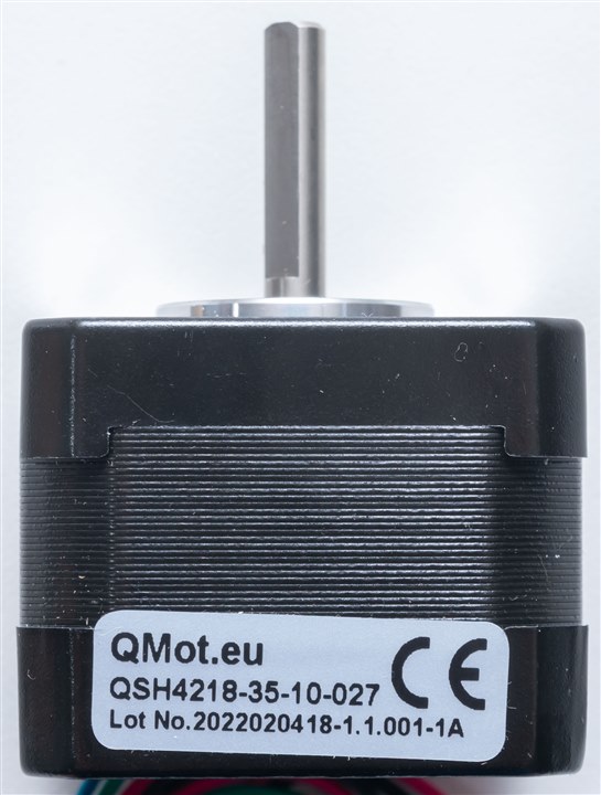
The motor is marked QMot.eu and has a model of QSH4218-35-10-027, which is apparently now an ADI Trinamic product. Based on the hardware manual, I was originally expecting a motor with an encoder, but this one doesn't have the encoder. Otherwise, it should be identical in functionality.

The TMC5272-EVAL-KIT comes in its own box, apparently assembled in Germany which is a rare find.
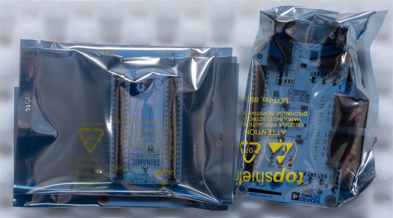
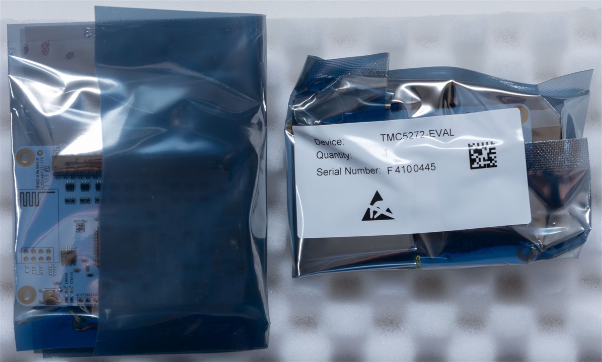
Inside, it seems three boards are packed into two static-shielding bags, carefully wrapped with egg-crate foam.
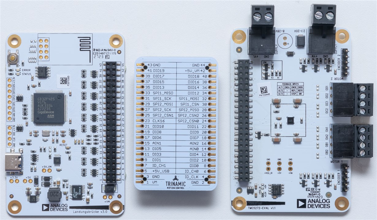
The three boards are as above - two of which have very decidedly-German names.
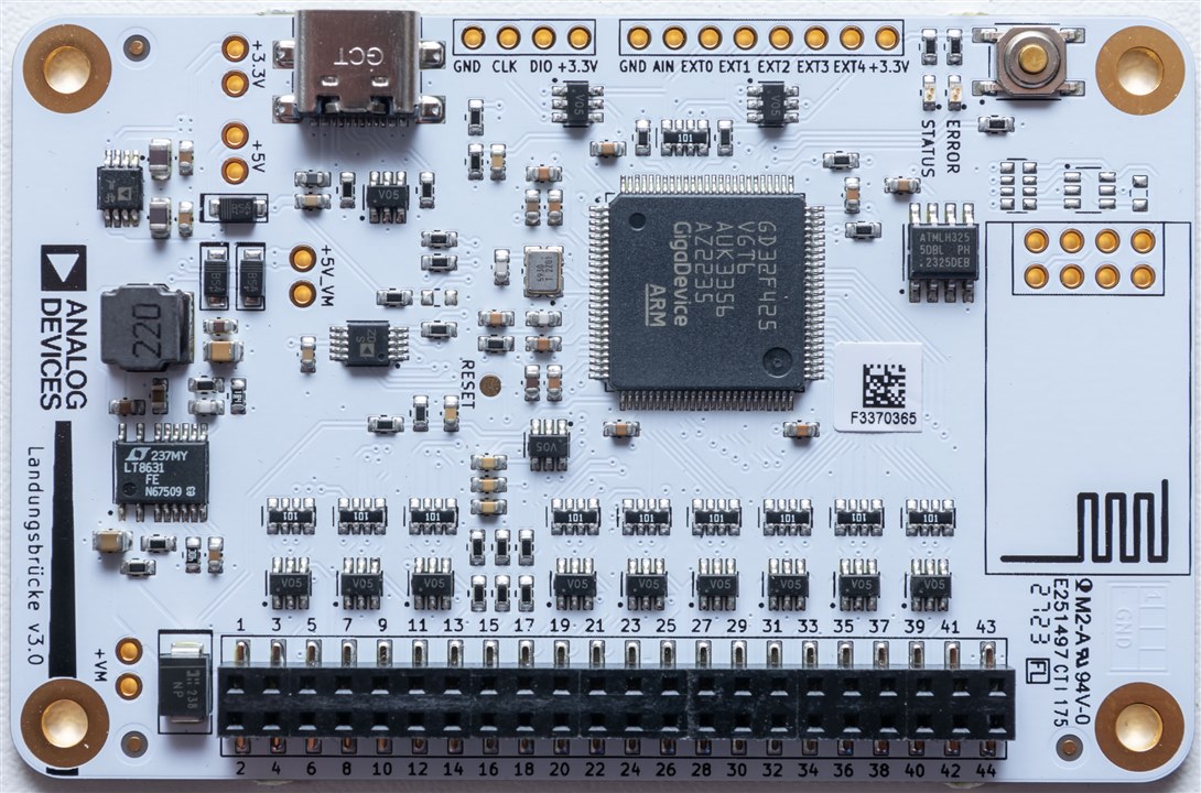
The board on the left appears mostly to be a computer USB interface board. It uses a GigaDevice ARM-based SoC to co-ordinate its operations and has a USB-C connection for data and power. There is a spot for an ESP-01 module for Wi-Fi connectivity, but this is not fitted. The name for this board? Landungsbrucke which translates into "landing bridge" or something similar. This is a fitting name, I suppose, given its function.
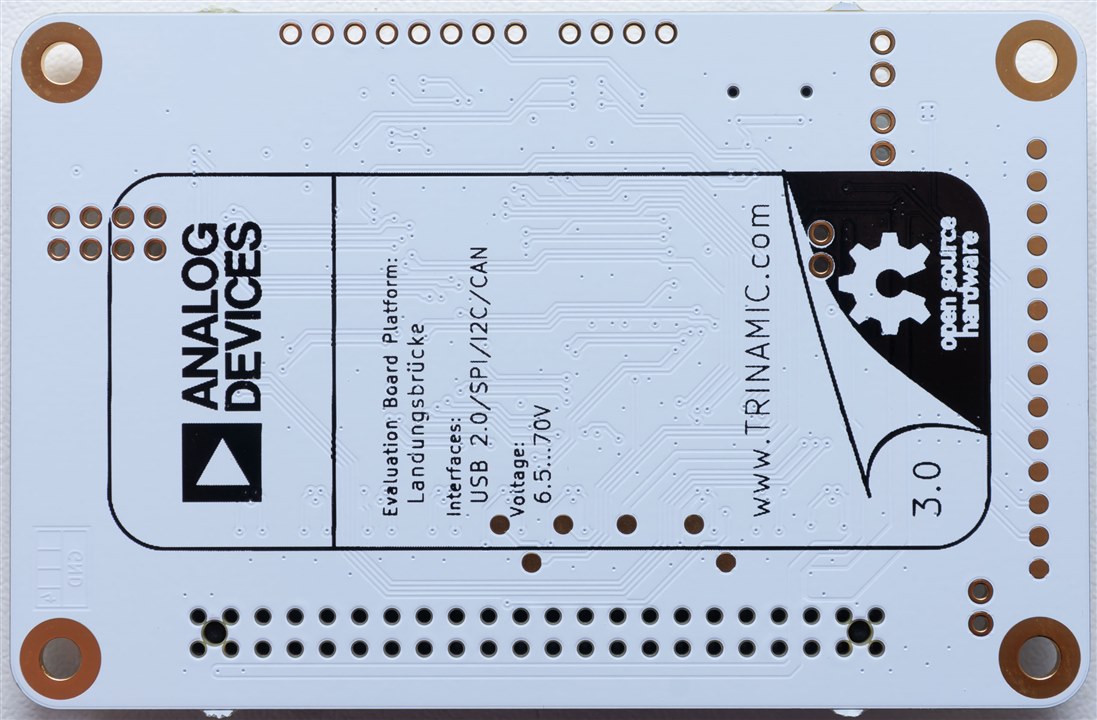
The board has a black silkscreen on white soldermask design and claims to be Open Source Hardware, which should mean that it's easy to modify and adapt for individual applications.
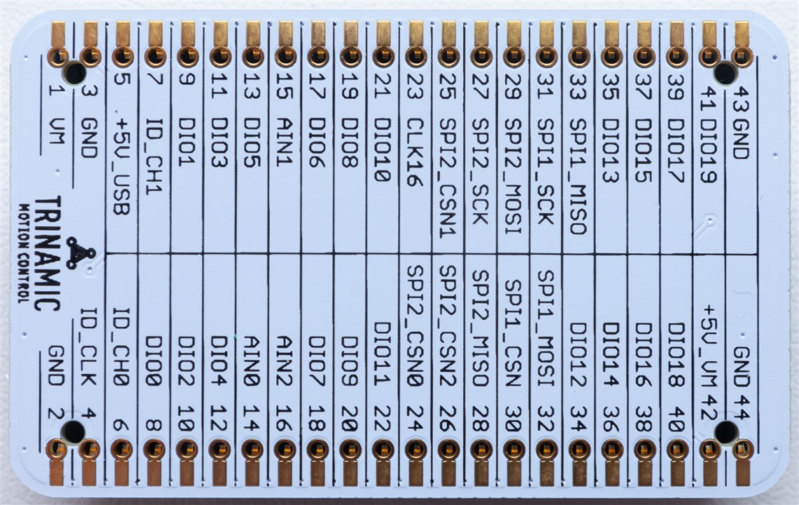
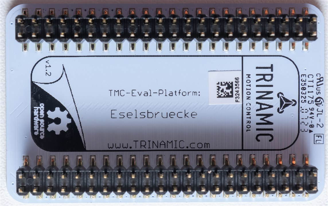
The next board is the Eselsbruecke which appears to directly translate to "donkey bridge" but also "mnemonic". It's function is a bridge for signals between boards, but perhaps the mnemonic function is the labelling of the signals. Or perhaps I'm just reading too deeply into this.
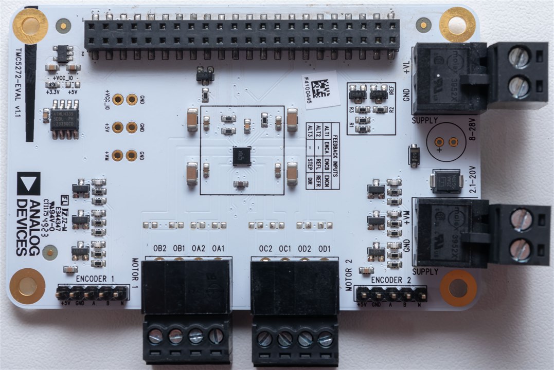
The final board is the stepper board itself, the TMC5272-EVAL. This particular board shows just how amazing the stepper driver chip is - just the small black square package inside of the black border. Apparently supporting two bipolar motors and two encoders, with up to 20V 0.8A drive. The size of the IC and the supporting components is just amazingly small.
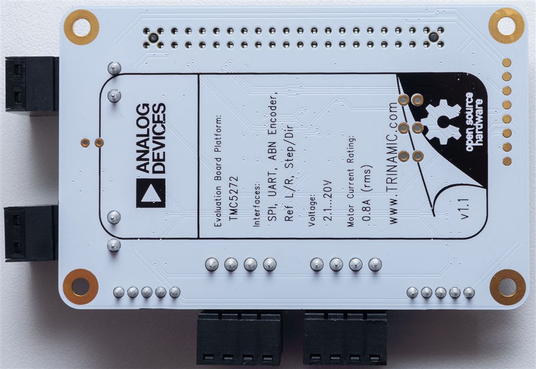
I didn't detect any German-names on this board, which was a slight disappointment. But that's okay - I've already seen a lot more here than I normally do.


One thing I really appreciated about the board is the fact they didn't skimp out on the use of pluggable terminal blocks to make connecting and disconnecting connections easy. That being said, we are warned not to do this when power is applied - back EMF can be quite the risk!
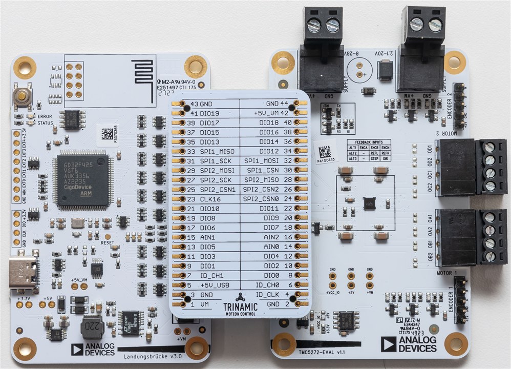
I suppose this is how the three boards come together, with the headers lined up and pushed into place. One thing that annoys the perfectionist in me is just how the board edges and holes on the left board don't line up with the right board once they're snapped together. They're offset by a few millimeters. That won't affect the function, and seeing that these boards are not really intended for end-product usage, I suppose it's not a big deal as long as it doesn't annoy you when you're testing it.
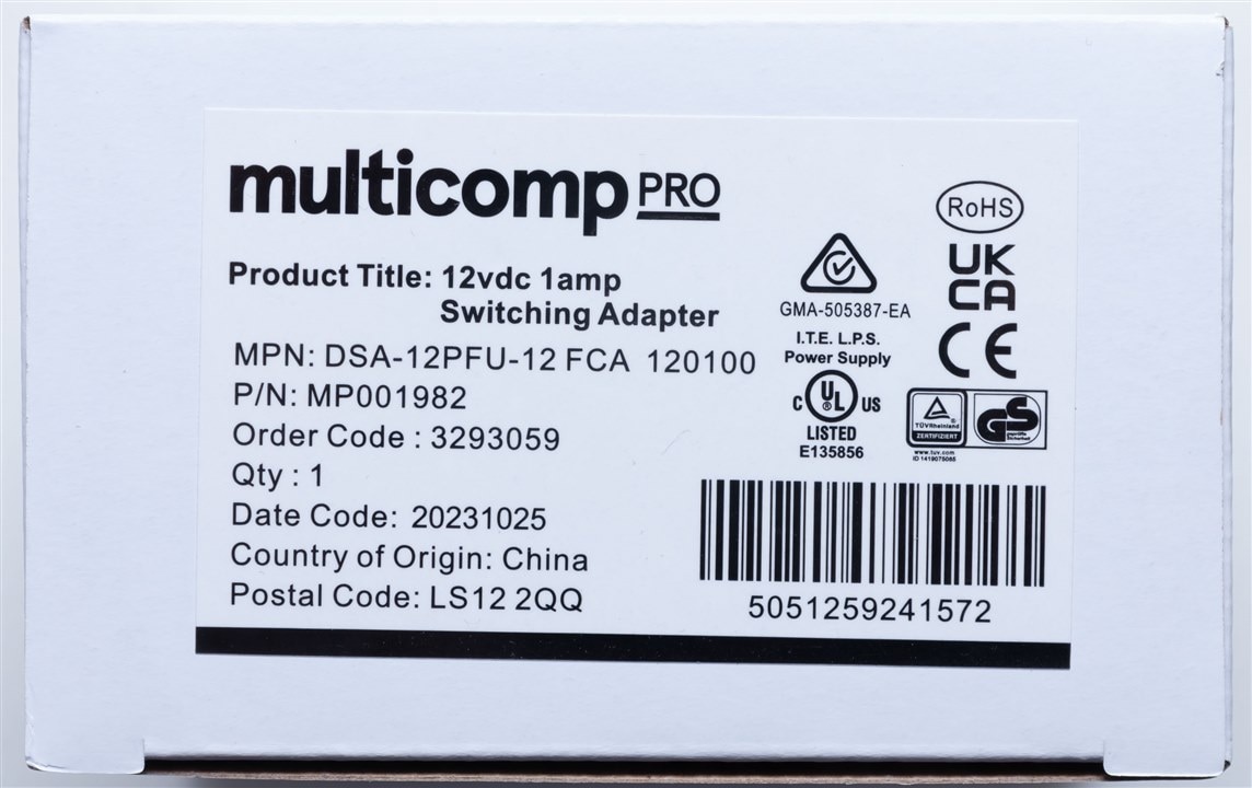
Finally, we come to the included 12V 1A DC power supply from Multicomp Pro, an element14 brand.
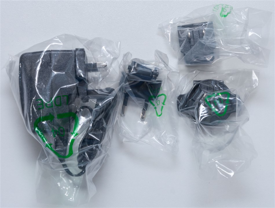
Opening it up, I already like the fact there are multiple plugs for different countries and Australia is included!
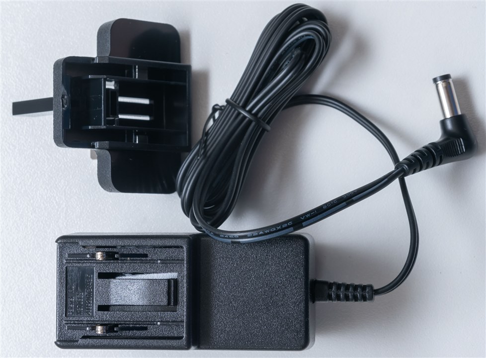
Swapping plugs was rather easy, pushing down to release a tab that allows the plug module to slide out and a new plug to be clicked into place.

The output appears to be a 5.5mm outer diameter, 2.1mm inner diameter DC barrel plug, although this will need to be removed for use with the kit.
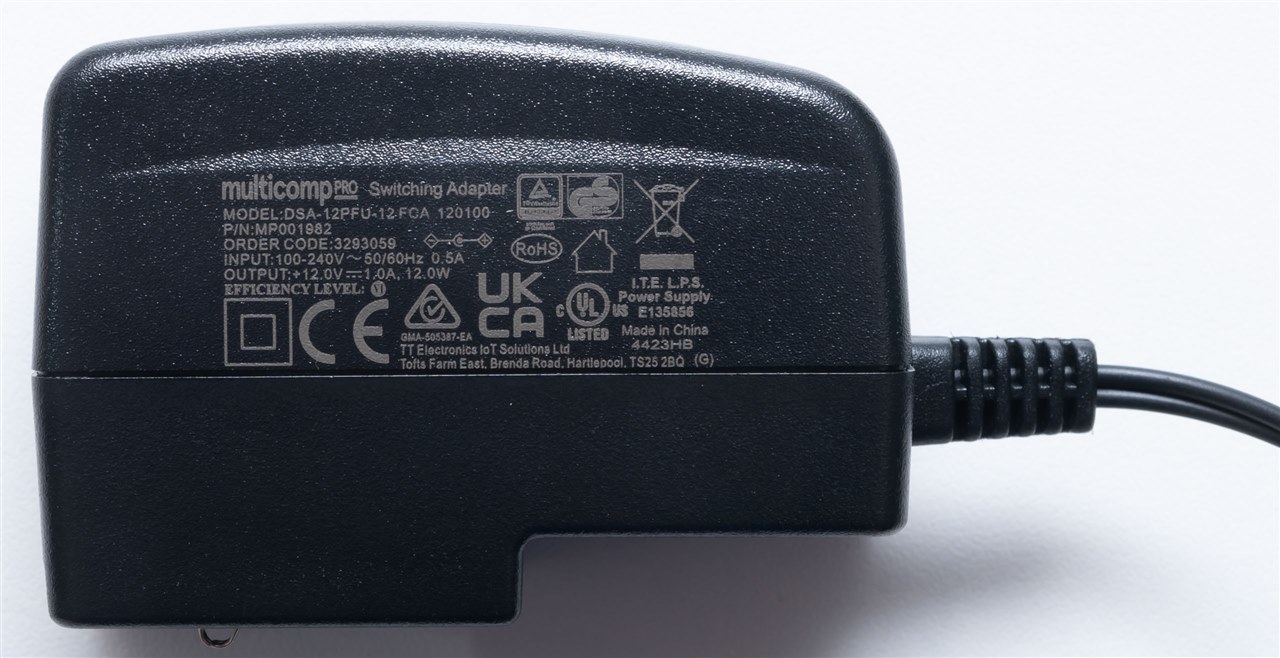
The specifications and ratings are printed on the side, along with all of the inclusions. The model is DSA-12PFU-12FCA 120100 with a part number of MP001982 and order code 3293059.
Connecting the Motor
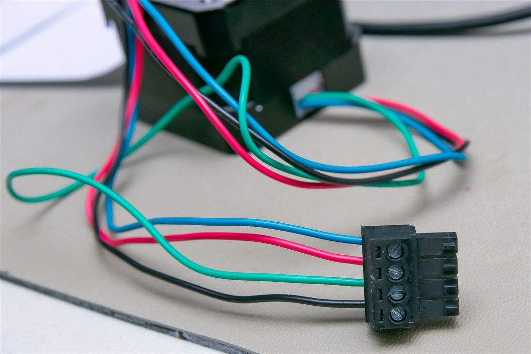
In the last section, I unboxed the motor which had four wire connections. This was a little new to me, as I used to recall steppers having six wires. This is because this is a bipolar stepper, as opposed to a unipolar stepper that has centre taps on each winding. For a better explanation of the differences, this page seems to be a good reference. But I suppose what it means in practice is that the driver needs to drive both coils both positive and negative, thus two H-bridges are needed at a minimum for the two windings. Thankfully, we don't have to build them discretely.
The connections on the PCB are marked OA1, OA2, OB1 and OB2. I can only surmise this to mean A phase and B phase connections 1 and 2. I don't have any real experience with these motors, but I suppose the distinction is somewhat arbitrary as to which phase is A phase and B phase, as long as the coil directions are correct. The motor itself, according to the datasheet has A+ as Black, A- as Green, B+ as Red and B- as Blue. Allocating A-phase to A and 1 as +ve, with 2 as -ve, this gives the following connection order:
Power Supply
As mentioned in the previous post, the connector on the power supply is not suitable for this kit, so it would have to be cut-off. Then, we had the interesting dilemma - what is the polarity of the wires? A quick check with the DMM appears to confirm that the supply has the striped lead as negative.

As a result, with the plug turned upside down so the lead markings are visible, I believe this to be the correct connection for the board.
However, it is probably not the ideal supply for the kit - according to the stepper motor datasheet, the ideal value for a chopper-based driver is somewhere between 4 to 22 x Ucoilnom which is 5.3V for my motor. This suggests a 24V supply may be better (using common voltages). The problem is that the single voltage input for the kit is limited to 20V, so unless you have two supplies, then it's going to be out of range. On the other hand, perhaps 20V isn't quite as hard to get - USB-C PD can supply it, given a >45W supply, but even that is a bit marginal. I guess the only limitation given the power supply is a limitation in motor velocity or torque attainable.
Installation and Setup

I'm running on Windows, so I downloaded the latest version of TMCL-IDE from ADI Trinamic's website here. At this time, it is V4.5, but at the commencement of the challenge it was V4.4, so it seems it gets regular updates.
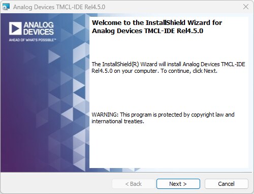
Installation is a case of following the wizard. Afterward, the software is installed - the default directory is "C:\Analog Devices\TMCL-IDE-Rel4.5.0\V4.5.0"
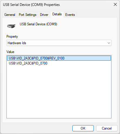
Plugging in the USB-C connection, the Landungsbrucke is automatically installed and comes up as a USB-COM port with the above VID 2A3C (Trinamic Motion Control GmbH & Co KG) PID 0700 (Evaluation Device) pair.
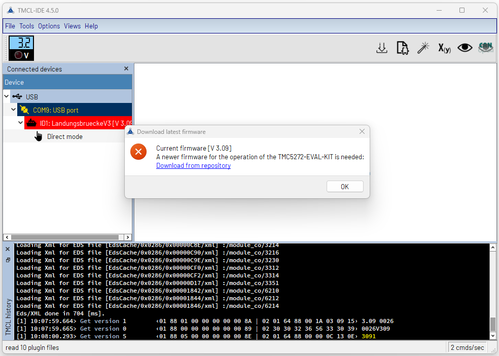
Starting the software tells us the firmware on the Landungsbrucke is out-of-date and to download new firmware from here. Make sure you download the corresponding version of file - in my case, the V3 file.
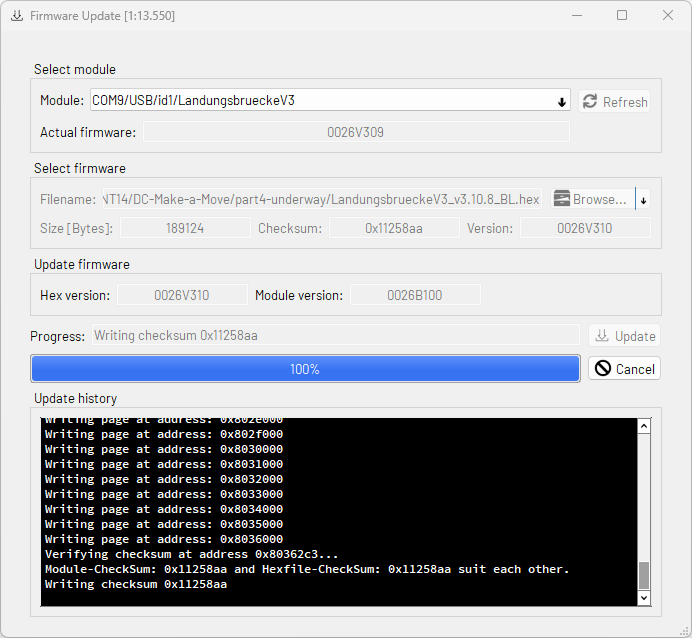
Then, the board can be flashed using the firmware update tool. It takes a minute or two and then the board automatically resets.
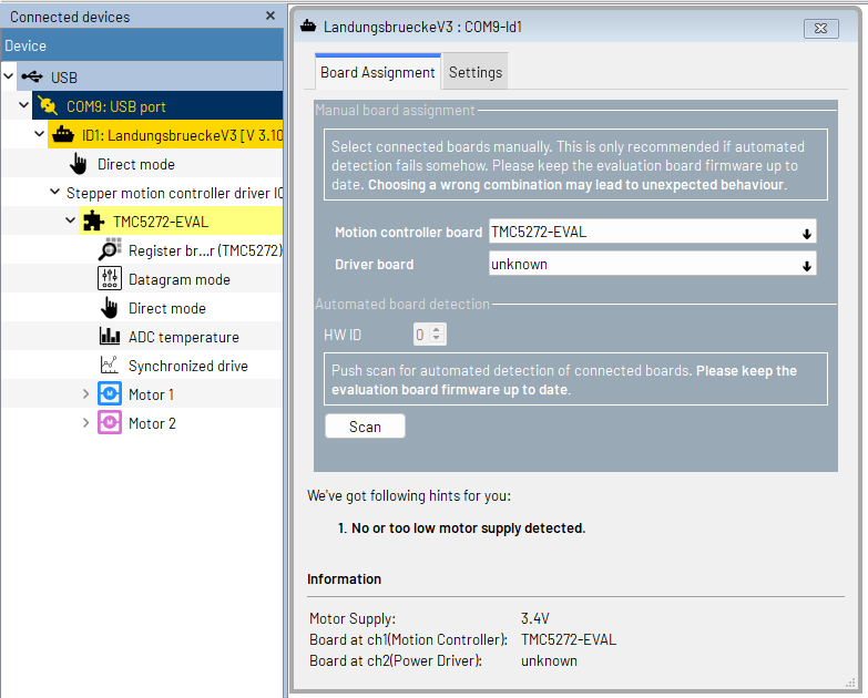
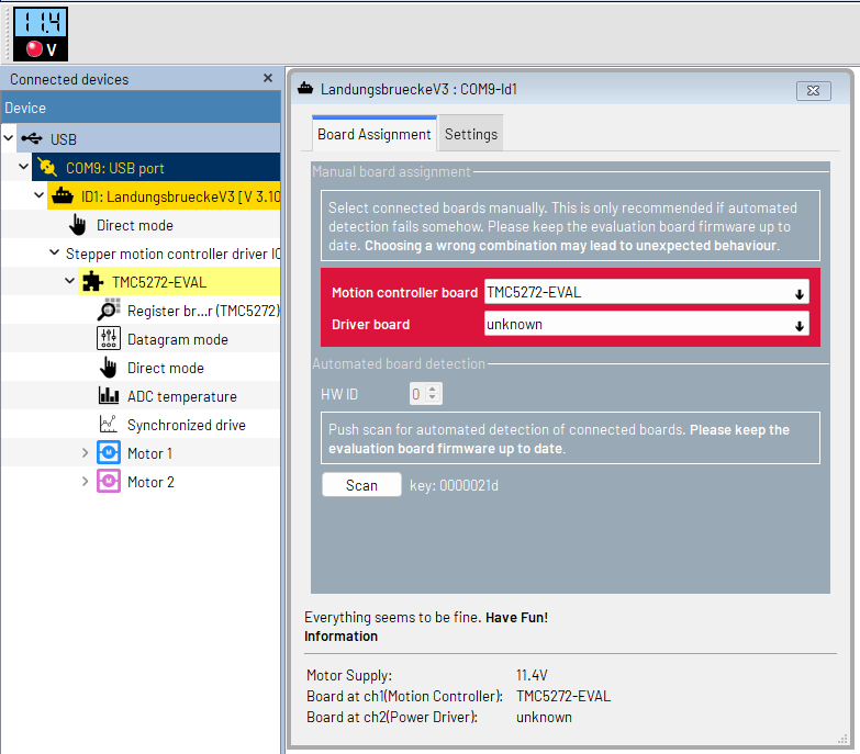
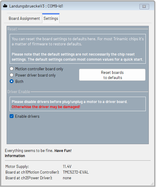
If you start with the power supply off, as suggested by the manual, the system will detect the board and the driver board then complain there isn't any motor supply. Turn the power supply on and voila - it's all ready to go. The IDE seems to default to automatically enabling the drivers, hence the warning to not unplug or plug motors to the kit when it is on, as it can cause damage.
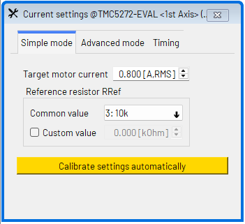
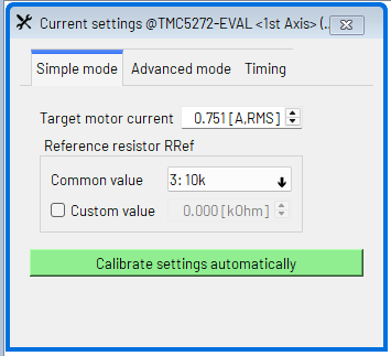
Looking at the guide, it seems that setting the current was the next step. Choosing the reference resistor to be 10k is the best option to enable the maximum current of 0.8A RMS, as the motor itself is rated for 1A. However, when I did this and hit the "Calibrate settings automatically" button, it complained that it can't reach the full current and the resulting motor movements seemed to have low torque. I suspected it wasn't running the right current, but reducing this to 0.75A seems to change the button to green and no warnings appeared. So it would seem that the chip might not be able to run at the full rating in the way it is configured, but this may be the closest we can get.
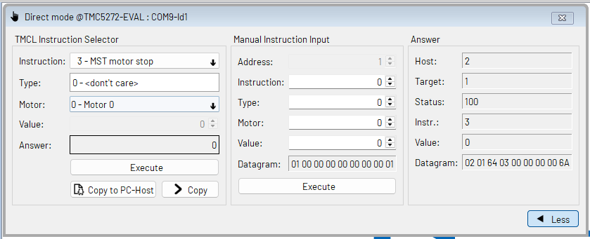
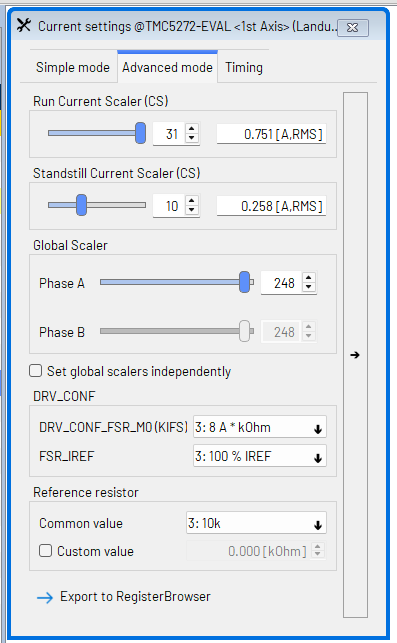
The IDE has a lot of useful, albeit, sometimes intimidating features. For example, the advanced configuration for the current gives a few more options, while the box to send raw commands gives a lot of freedom but doesn't give a lot of guidance.
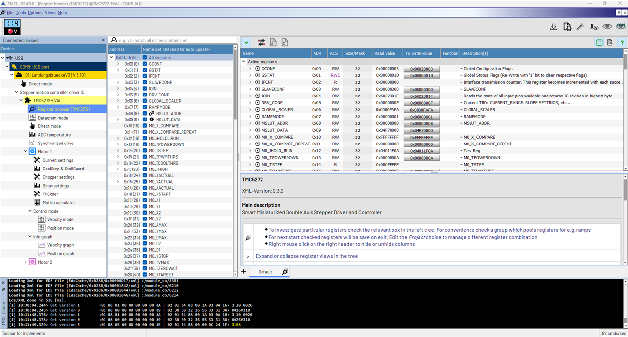
The register table is amazing though - lots of information here and the possibility to monitor the values as well. This really is a lot easier to work with than the datasheet alone.
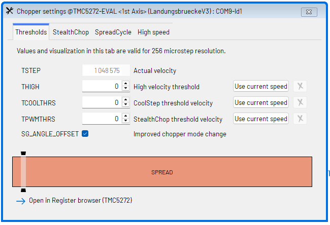
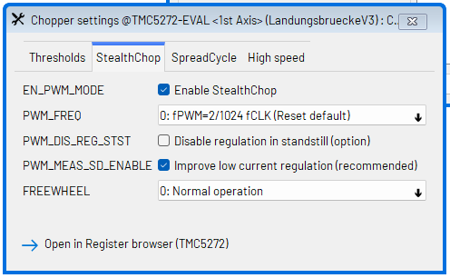
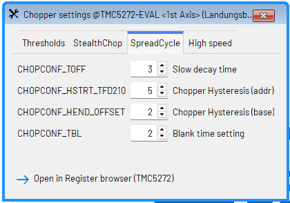
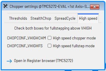
Chopper settings allows for changing the StealthChop feature on or off. This has the effect of mitigating some of the classic stepper noises from the motor by controlling the driving waveform and frequency. I'm not quite sure how to set the appropriate threshold settings, and as a result, I do get some strange positioning undershoots when turning it on. Perhaps it's my incorrect settings that are causing the motor to miss steps.
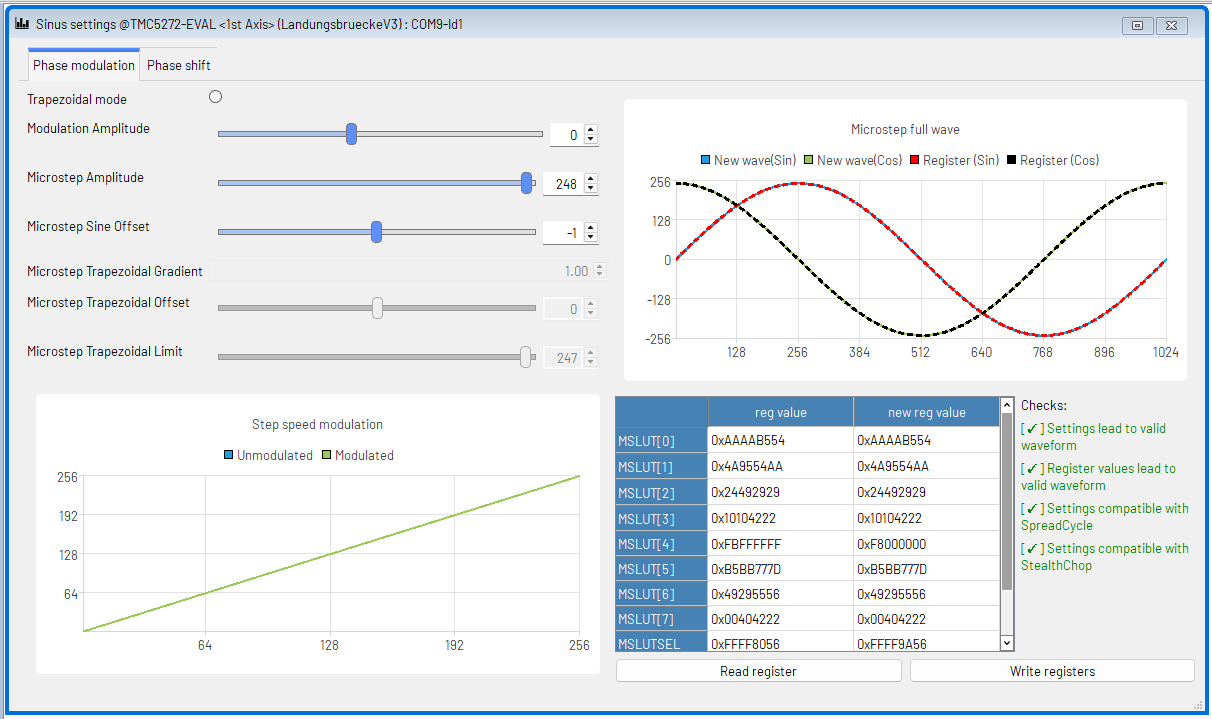
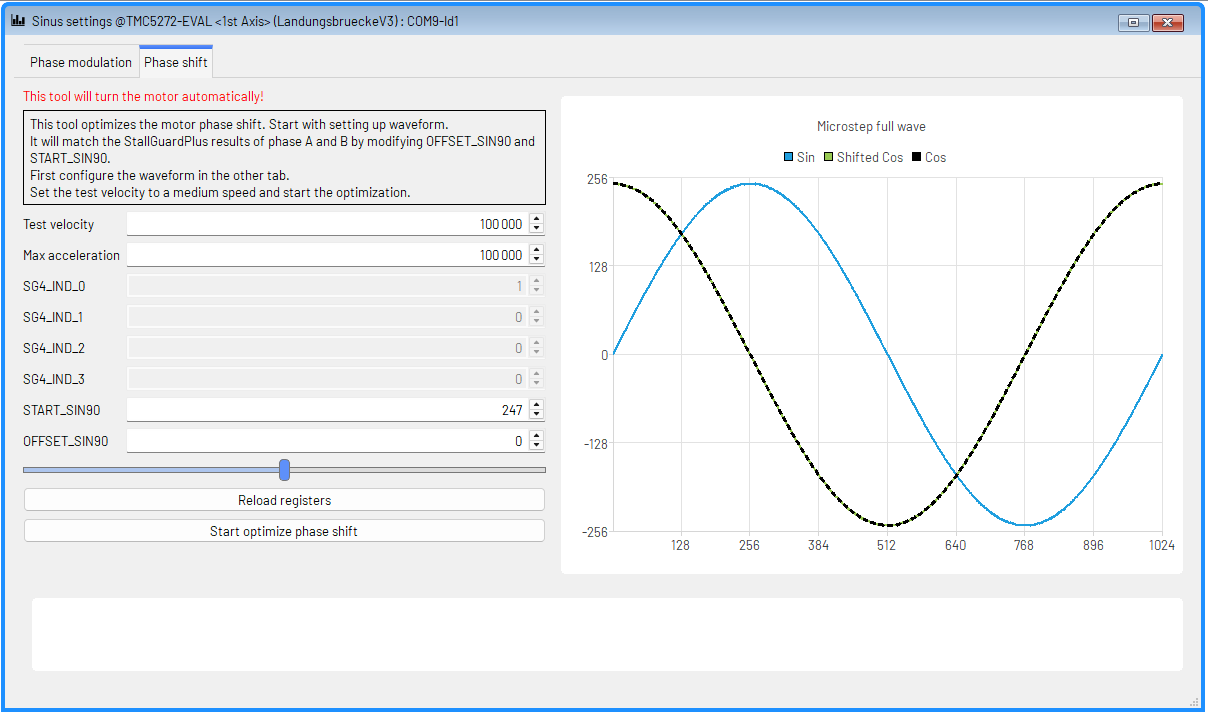
The Sine settings dialogue allows you to tweak the driver's waveforms. There is also an automatic tuning feature that tunes the phase offset between windings for better StallGuard performance.
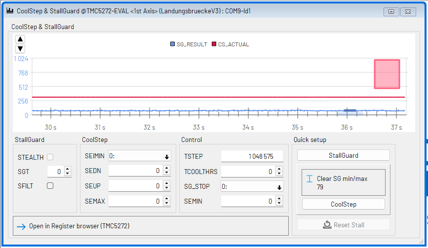
As far as I can tell, StallGuard is a feature for sensorless detection of an impending motor stall, potentially avoiding step-loss and allowing for sensorless stepper applications. It seems that this dialogue is used for testing the stall-guard values that need to be set under application load to determine when a stall should be detected. While a simple idea, getting this to work reliably in practice is a bit of a challenge. I tried stalling the motor manually, causing step-loss, but depending on the situation, sometimes it would show something while other times it did not. It seems it's not a system that works well at very high or very low speeds for "hard" stops based on FluidNC's Wiki, and a few steps lost appears to be not-unusual.
Movements
Time to get it moving. Two of the main modes are Velocity Mode and Position Mode. Velocity mode is as it sounds - it controls the speed of the rotation and the acceleration used to get there.
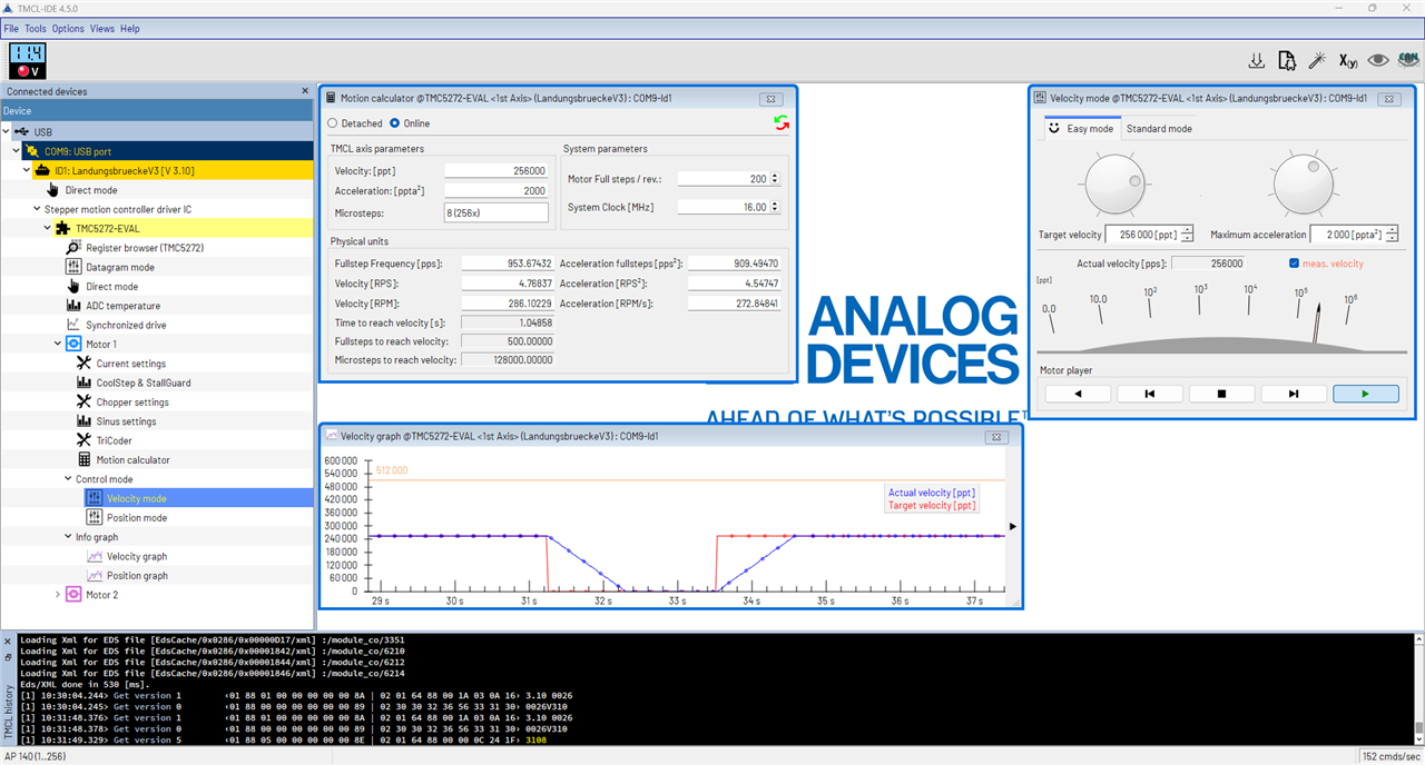
The system allows you to configure the relevant speed and acceleration values, with a graph showing the actual values the driver is generating. Using the motion calculator also allows you to translate the stepper-motor driver units into something more "human".
The second mode is the position mode, which is perhaps the more useful mode for some applications which rely on the stepper's behaviour to move a precise number of steps (or microsteps).
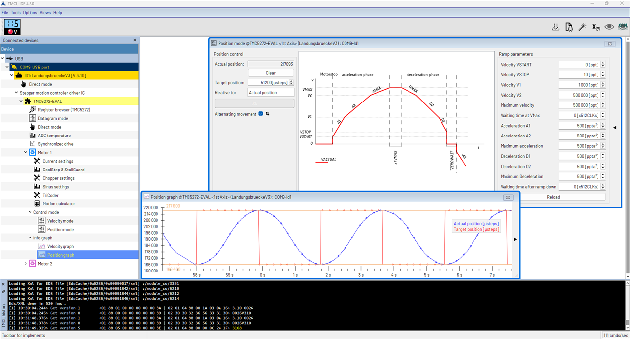
In this case, I was able to program in a "wave" where the stepper turns in one direction a full rotation, then back in the other, with smooth acceleration/deceleration such that the motor's position is changing nearly perfectly sinusoidally.
Here's a quick video of this happening:
Does It Get Hot?
Surprisingly, no. Not really. Then again, it's not driving a heavy load - just its own inertia and a tiny bit of electrical tape, back and forth.
The Landungsbrucke is hotter than the driver board!
The driver chip up-close isn't particularly hot either.
Turns out, the motor is the hottest part of it all!
Integration
From here, to use the driver in a practical application, there seems to be two ways forward.
One potential way is to use the Landungsbrucke since there is a full TMC-EvalSystem firmware sources available and the bootloader nature of the firmware also means that no special programmer is necessary - TMCL-IDE is all you need. To actually get developing will require Eclipse IDE and GCC toolchain to be set-up, and I suppose it would take some effort to understand the code that already exists, much of it going to support other boards that are not the one we are using. As I'm not particularly familiar with the Gigadevices MCU and the HAL functions, I decided that this probably isn't my preferred path, but it is an interesting one as it truly makes it an evaluation platform, rather than just a simple piece of demonstration kit.
The other way would be to talk to the TMC5272 directly over its SPI or 1-Wire UART interfaces. Thankfully, rather than starting from scratch, ADI Trinamic have a TMC-API which provides a C-based vendor-agnostic code that can be glued into your platform of choice by writing the necessary call-back functions to provide higher-level control of their stepper drivers. This is like having an Arduino library at hand, just that you need to "teach" the code how to access the hardware of your platform. That's a nice compromise. As for hardware connectivity, it seems SPI would be relatively straightforward, however, for a large number of motors, 1-wire UART would be more efficient as it supports multiple drivers on the same line. It's a strange hybrid between I2C's open-collector bus and regular UART, allowing it to be "shared". But because of this, there are some considerations, especially that all TX lines should go high-Z when done, so that may introduce some timing constraints. Perhaps it'll be SPI for me.
Finally, this has me thinking about just how to implement this for my Variac. The Variac has hard stops at each end and StallGuard might be usable to detect the end-stops as the spinning resistance of the wiper and the hard stop should be sufficiently different and no harm will happen if the torque is limited by a reduced drive current (and hopefully, any mounting hardware will be durable to the torque too). But having read that it's not good at low speeds has me slightly worried. What if the motor is already at a limit and is trying to find the limit - will it work? Or will it be reliable? I presume this means, after every power loss, the system will have to sweep the Variac's full range, which wouldn't be nice to any connected load and also adds wear to the carbon brush.
Another thing is whether I drive it in position or velocity mode. I think my application is better suited to position mode, as there's about 270 degrees of travel at the most. But this is where things get complicated, as amount of turn for a given voltage increase or decrease depends on the input voltage on a Variac, which is the quantity that is varying and not being directly measured. So perhaps this means I have to either take a naive approach and do fixed steps up or down and repeat until the result is in the desired range (in which case, it feels like I'm going the quick-way-out and it's almost like using a step/direction input and thus losing all the smarts). Or I will need to compute, based on the step number, the transformer's ratio at the time a voltage reading is taken, then back-calculate what the input voltage would be, then calculate the target ratio that would give the desired voltage, then compute what step number that would be, then drive to that location. I think this is a more sensible approach, but it depends on the ratio computations being very accurate (and thus, perhaps a fine-tuning loop might be necessary too). Having the ability to adjust a dead-band to avoid needless moves is also important, as I won't want to "burn out" the carbon brush with too many needless moves.
Another issue simply is that the Tektronix PA1000 Power Analyser only gives a voltage reading twice-a-second. This means that the opportunity for compensations will be limited, so we want to make the best compensation we can at each step. Unless I build my own mains-waveform-sampling input, which could theoretically go down to "per-cycle" levels of feedback, but that is a potential danger.
Finally, I would still need to design a chassis to hold the motor and a coupling to somehow connect the two round-ish shafts together. While 3D printing is likely going to be the only means I have for this, whether the material will be strong enough to withstand repeated StallGuard trips to find the rotation limits, whether I can even get the right size/shape to fit as the Variac isn't designed for any mounting on the top surface, are all going to be challenges. Perhaps I have bitten off more than I could chew ...
The Variac
The unit in question is an old Yamabishi Electric Variac from Japan. This was a purchase from a ham-fest many years back, so it’s nothing particularly modern, so safety isn’t exactly high on the list of features.
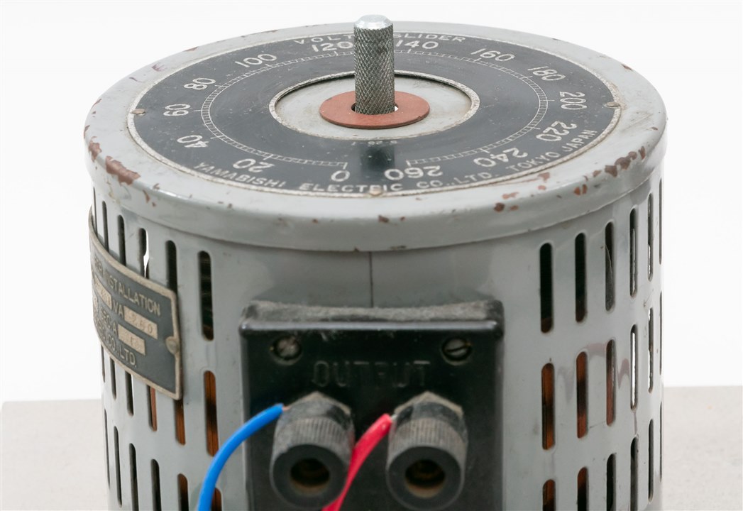
Nevertheless, after removing the grub screw and removing the knob, I found the centre shaft to be 8mm in diameter with knurling. The shaft protrudes 18.5mm from the surface of the Variac. There is no flat-section on the shaft, being entirely round. The top surface of the Variac didn’t have any mounting holes, so there is nowhere to directly anchor the stepper motor.
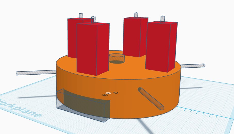
As a result, I decided that I needed to design a “hat” to fit over the top 117mm diameter surface of the unit and hold itself in place with some screws pushing on the metal surface of the casing and using the rectangular surface near the terminals. That way, it would be like a “hat” sitting on top of the Variac.
In order to do this, I drew up a quick design in TinkerCAD to accommodate this, but also to adapt this “hat” up to a new mounting surface which would be just the right height to keep the stepper and Variac shafts centred and not quite touching one-another.
Stepper Motor
The stepper motor is a NEMA17 style motor. As a result, it has a square form factor with M3 mounting holes spaced 31mm apart. They appear to be tapped to a depth about 4-5mm. The motor body itself measures 42mm and is 33.5mm deep. The shaft measured 5mm diameter with a D-cut profile with 20mm of height. The shaft raises 24mm from the body of the motor, including the 2mm raised portion of 22mm diameter.
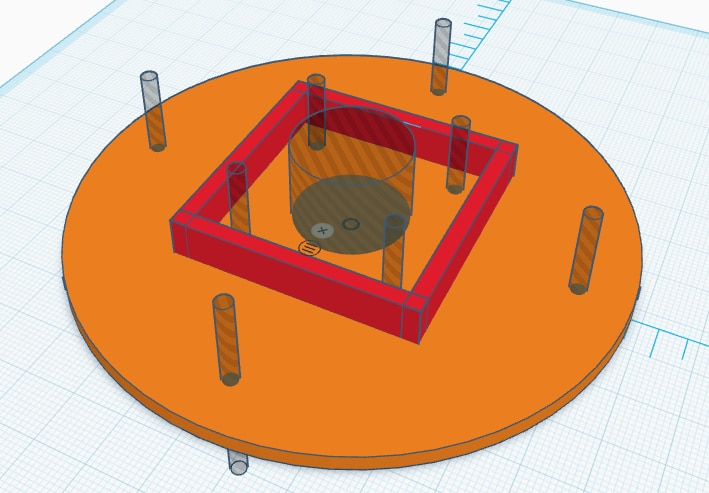
To adapt this, I have a flat, round plate of 3mm thickness with the mounting holes for the NEMA17 style motor and a barrier surrounding the motor itself to add additional strength. I felt this was necessary to ensure that any over-stress doesn’t destroy the adapter.
Coupling
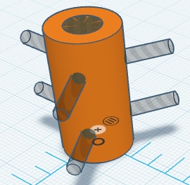
Coupling two round shafts together is a bit of complex business, as they might not be perfectly aligned in the centre. Nevertheless, not having any access to mechanical hardware like belts and pulleys or spider couplings, I decided simply to 3D print a “tube” with the provision for screws to add additional clamping force. It’s not high-tech and it won’t work for high torque, but perhaps that’s a “feature” and not a bug, in case of any unexpected accidents.
3D Printing and Fitting
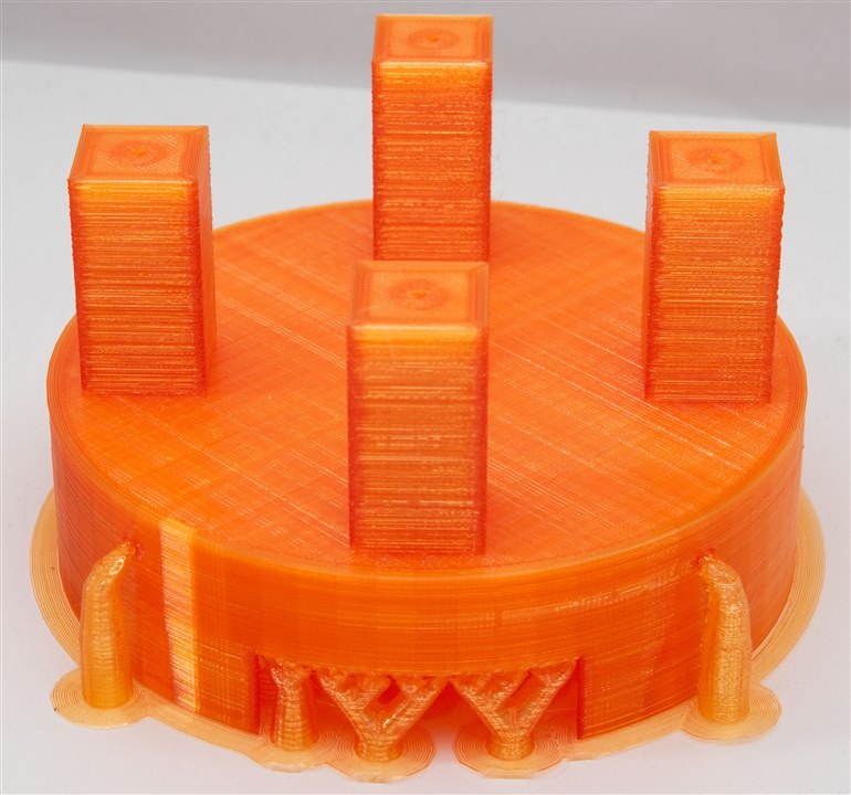
After designing it, I decided to employ my 3D printer to manufacture these parts and see if it would work. My printer is a bit old and the belts are a bit sloppy, given the short time remaining, I’ve pushed the speed to the absolute maximum.
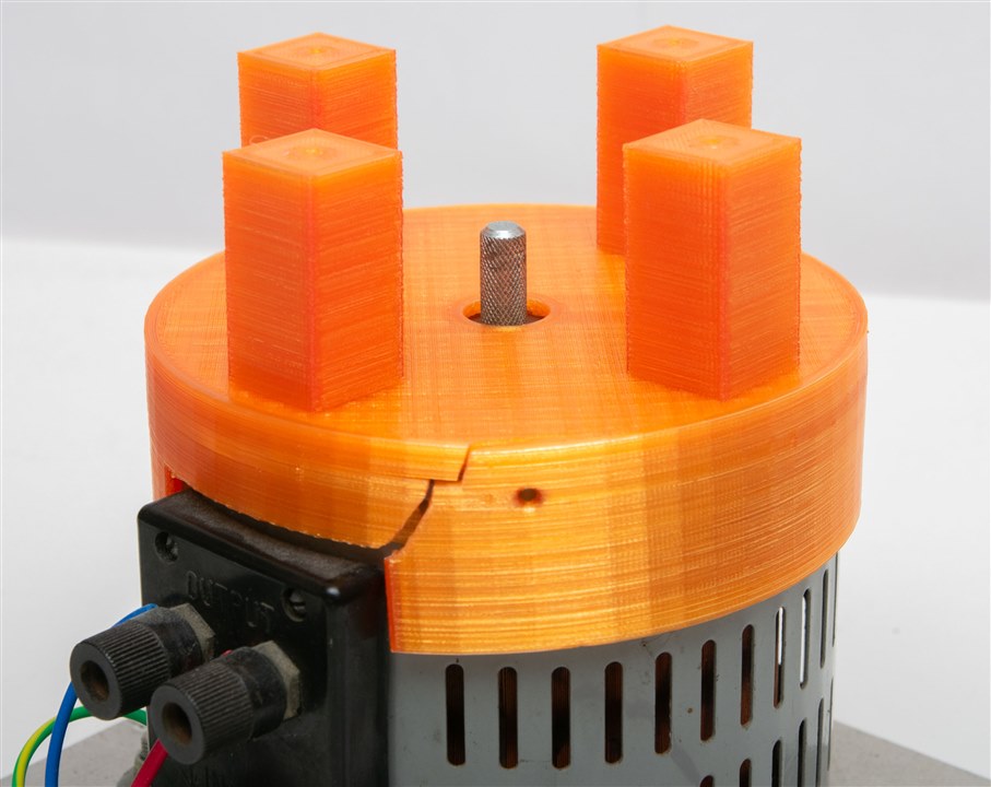
The “Variac hat” was supposed to be a tight fit, but this was too tight. After tapping it a few times with a hammer, it split along the side. It’s still tight on the unit, although this does mean that there might be a bit of off-axis alignment when fitting the stepper.
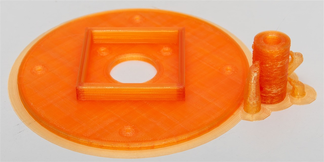
The stepper plate and coupler were printed as a second job due to bed space limitations.
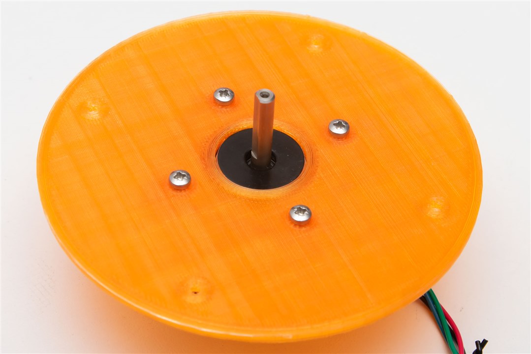
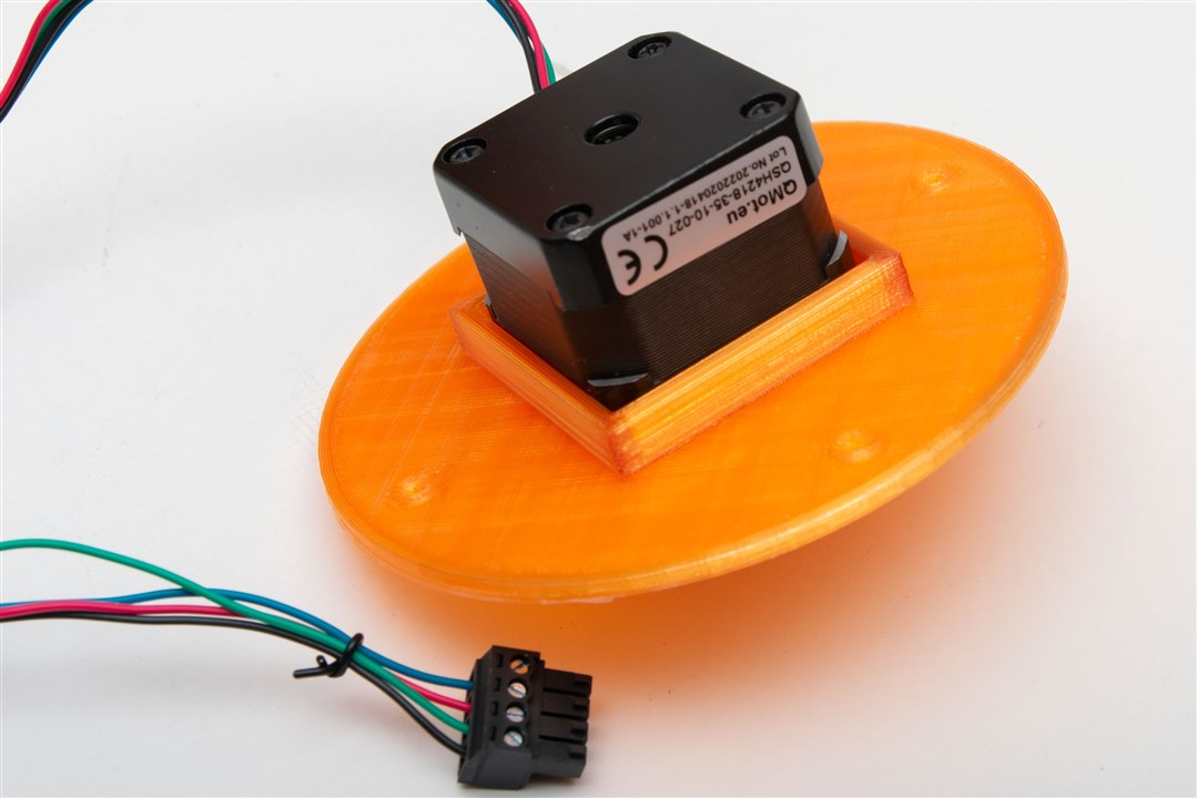
The motor fits well within the plate.
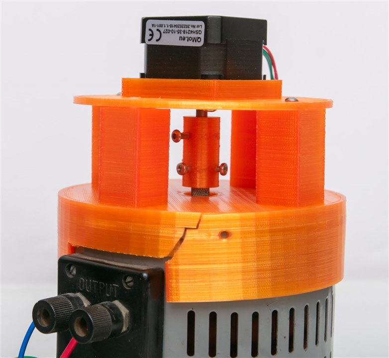
The coupling needed to be cleaned out with a drill bit to get to the right diameter. Unfortunately, once the coupling had both shafts inserted, it was evident that the two axes were not quite aligned, resulting in difficulties getting the top plate installed.
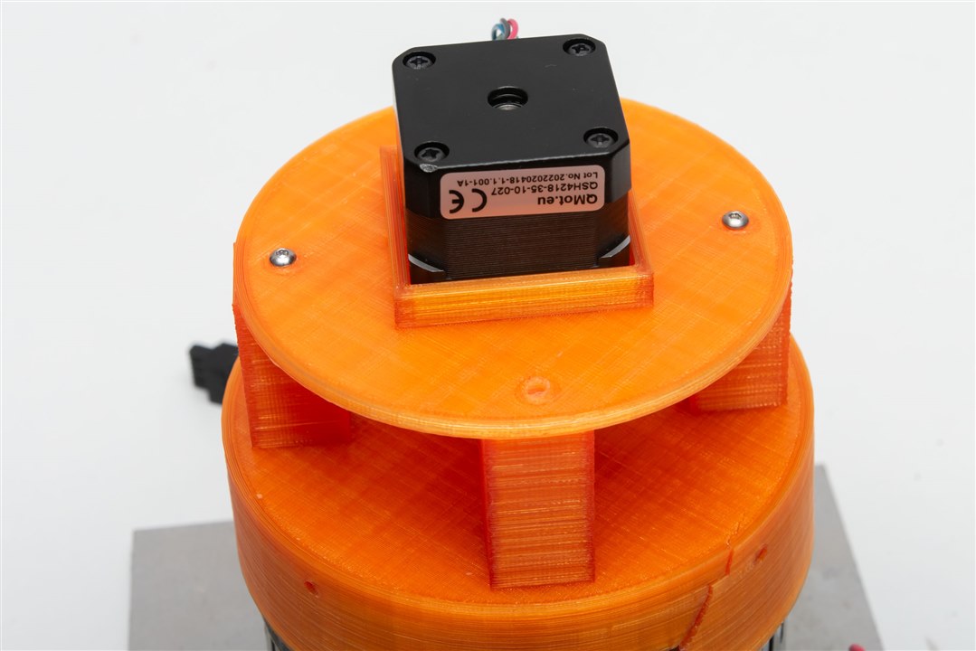
As a result, just two screws were used to secure the top plate to the hat, alongside some reaming of the screw holes to provide a bit more adjustment room. The coupling was unfortunately not very tight on the Variac side, leading to the potential for slip. Using plastic and having machine screws cut threads into it doesn’t result in much strength. This might protect the Variac from over-torque damage, but it does mean that step-to-ratio correspondence may not be maintained. The design also doesn't have a defined way to detect the end stops (e.g. by limit switches) and would instead have to either naively bump into an end stop repeatedly to guarantee a position or use StallGuard.
Attempting to run the board today, it seemed that the Landungsbrucke didn’t detect the driver. Even pressing scan didn’t work, but manually selecting it seemed to restore it to operation.
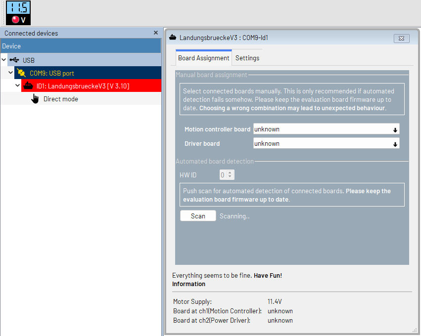
Not sure what went wrong – it was automatically detected previously. Perhaps I have a bad/broken connection somewhere.
Testing with the board shows the motor has sufficient torque to overcome the slightly stiff shaft of the Variac. The coupling does result in some motor resonances being coupled into the wiper brush assembly, which is probably not good for lifetime, but turning on StealthChop seemed to reduce some of them.
A Quick Attempt at Integration
Having seen the TMC-API implementation, I decided to try quickly porting it to Arduino and running it in a sketch. To do so, I needed to make sure the TMC5272.c, TMC5272.h and TMC5272_HW_Abstraction.h are ion the same folder. From there, I needed to add the following lines to the top of my code:
#include <SPI.h>
extern "C" {
#include "TMC5272_HW_Abstraction.h"
#include "tmc5272.h"
}
From there, it is a case of writing Arduino versions for their extern functions:
// => TMC-API wrapper
extern void tmc5272_readWriteSPI(uint16_t icID, uint8_t *data, size_t dataLength);
extern bool tmc5272_readWriteUART(uint16_t icID, uint8_t *data, size_t writeLength, size_t readLength);
extern TMC5272BusType tmc5272_getBusType(uint16_t icID);
extern uint8_t tmc5272_getNodeAddress(uint16_t icID);
// => TMC-API wrapper
Depending on if you use SPI or UART, I believe you can probably get away with a null implementation of the other. While I did get it to build and I connected the SPI bus between my Maker Pi Pico (with Raspberry Pi Pico RP2040), along with R2/R3 select pins, sleep, power and SPI/UART selection pins, I was not able to get a proper response. I even tried forcibly tying EEPROM_CS to high, but still no dice.
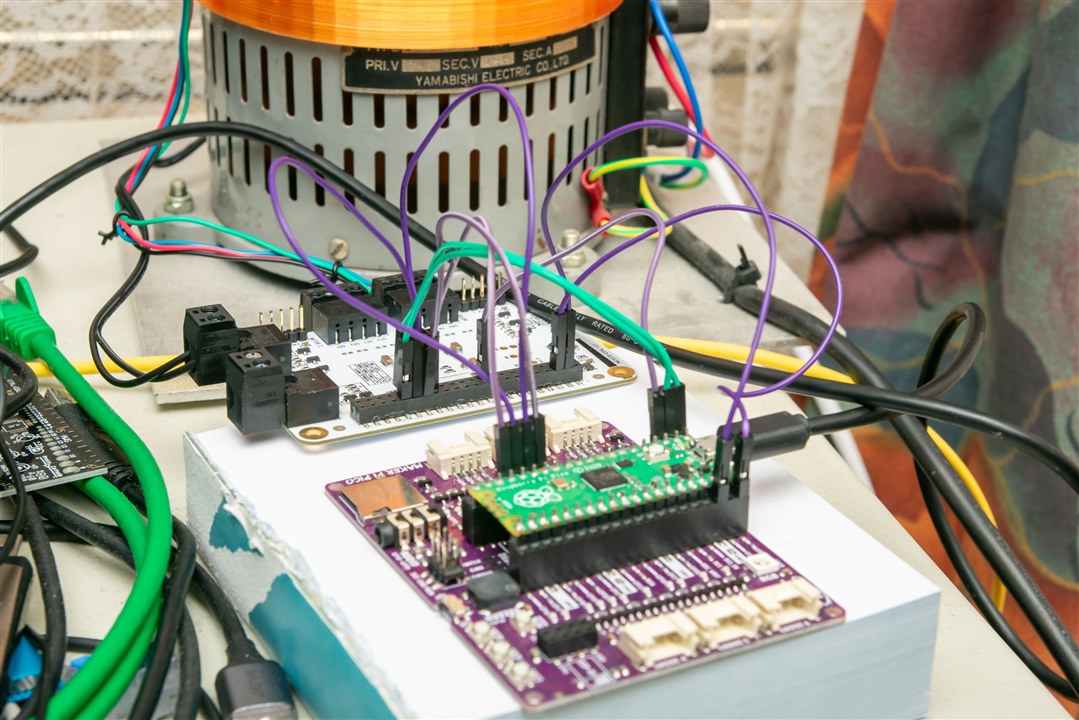
I'm sure I'm really close ... but I ultimately didn't have the time to debug this further. Could have been a few bad wires, or could be some unusual behaviour from my driver board entirely, or the wrong init sequence (even though I tried their example to no avail), or a bug in my SPI code (I tried a few variants, double-checked the pin allocation but stopped short of verifying signals on a scope). Anyhow, after this marathon effort, I'm willing to call it here. So close, yet so far.
Conclusion
Regulation of AC voltage is not a particularly easy task to achieve. Most Variacs (autotransformers) are designed to be manually actuated to change the transformer ratio, thus smoothly varying the output. However, by attaching a stepper motor, it should be possible to have this capability under computer control, making for the possibility of automatic voltage regulation without the jarring steps that most systems have. This project has attempted and demonstrated various parts that would be necessary for such a system, however, not quite reaching a final implementation due to running out of time for proper integration with the microcontroller platform of my choice. I do think that this is something that is achievable, provided the bugs are ironed out with the driver board connection to my microcontroller.
References
- AVR Part 1 - The Concept
- AVR Part 2 - Unboxing
- AVR Part 3 - Connections and Power
- AVR Part 4 - TMCL-IDE Setup and First Movements
- AVR Part 5 – Connecting Variac and Stepper


Top Comments