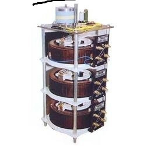
In this chapter, I’ll be looking at my last-ditch attempt to progress my “Make a Movement” design challenge in spite of my medical conditions. As I cannot walk, I’ve had to literally crawl around to make this happen. After all, the finish line is getting closer by the day.
The Variac
The unit in question is an old Yamabishi Electric Variac from Japan. This was a purchase from a ham-fest many years back, so it’s nothing particularly modern, so safety isn’t exactly high on the list of features.
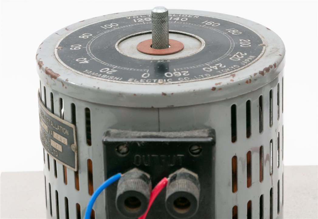
Nevertheless, after removing the grub screw and removing the knob, I found the centre shaft to be 8mm in diameter with knurling. The shaft protrudes 18.5mm from the surface of the Variac. There is no flat-section on the shaft, being entirely round. The top surface of the Variac didn’t have any mounting holes, so there is nowhere to directly anchor the stepper motor.
As a result, I decided that I needed to design a “hat” to fit over the top 117mm diameter surface of the unit and hold itself in place with some screws pushing on the metal surface of the casing and using the rectangular surface near the terminals. That way, it would be like a “hat” sitting on top of the Variac.
In order to do this, I drew up a quick design in TinkerCAD to accommodate this, but also to adapt this “hat” up to a new mounting surface which would be just the right height to keep the stepper and Variac shafts centred and not quite touching one-another.

Stepper Motor
The stepper motor is a NEMA17 style motor. As a result, it has a square form factor with M3 mounting holes spaced 31mm apart. They appear to be tapped to a depth about 4-5mm. The motor body itself measures 42mm and is 33.5mm deep. The shaft measured 5mm diameter with a D-cut profile with 20mm of height. The shaft raises 24mm from the body of the motor, including the 2mm raised portion of 22mm diameter.

To adapt this, I have a flat, round plate of 3mm thickness with the mounting holes for the NEMA17 style motor and a barrier surrounding the motor itself to add additional strength. I felt this was necessary to ensure that any over-stress doesn’t destroy the adapter.
Coupling
Coupling two round shafts together is a bit of complex business, as they might not be perfectly aligned in the centre. Nevertheless, not having any access to mechanical hardware like belts and pulleys or spider couplings, I decided simply to 3D print a “tube” with the provision for screws to add additional clamping force. It’s not high-tech and it won’t work for high torque, but perhaps that’s a “feature” and not a bug, in case of any unexpected accidents.

3D Printing and Fitting
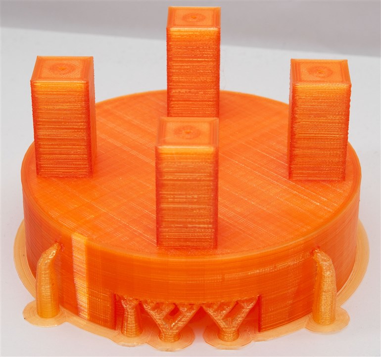
After designing it, I decided to employ my 3D printer to manufacture these parts and see if it would work. My printer is a bit old and the belts are a bit sloppy, given the short time remaining, I’ve pushed the speed to the absolute maximum.
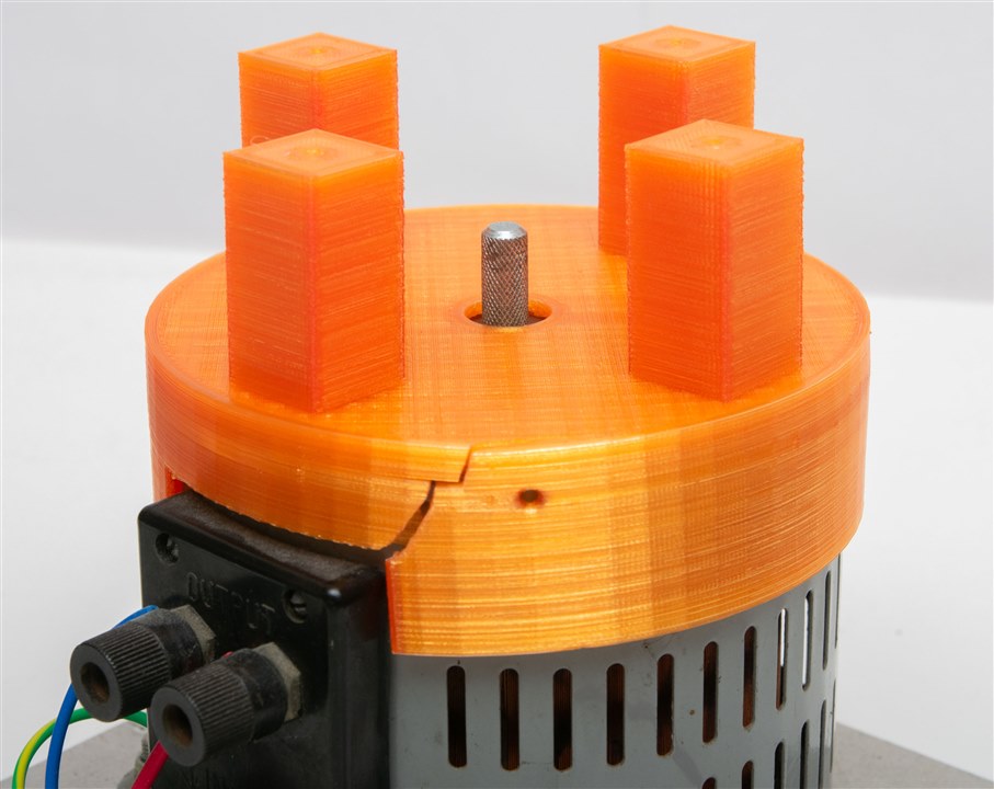
The “Variac hat” was supposed to be a tight fit, but this was too tight. After tapping it a few times with a hammer, it split along the side. It’s still tight on the unit, although this does mean that there might be a bit of off-axis alignment when fitting the stepper.
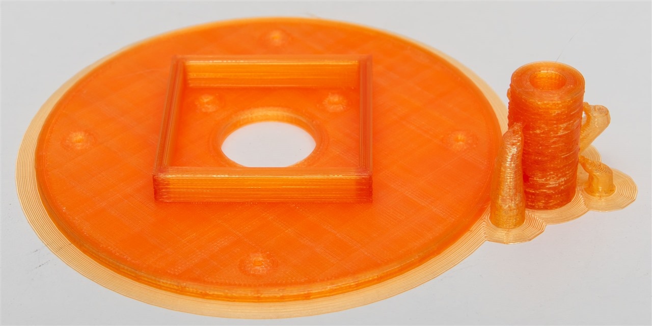
The stepper plate and coupler were printed as a second job due to bed space limitations.
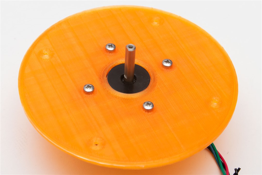
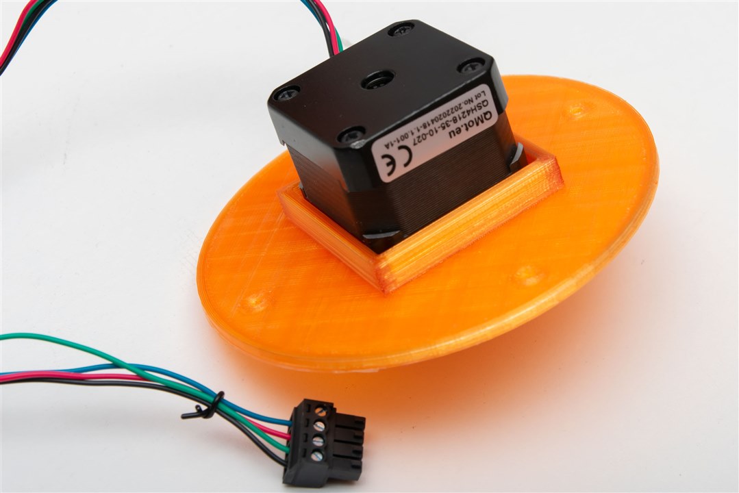
The motor fits well within the plate.
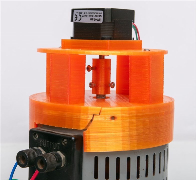
The coupling needed to be cleaned out with a drill bit to get to the right diameter. Unfortunately, once the coupling had both shafts inserted, it was evident that the two axes were not quite aligned, resulting in difficulties getting the top plate installed.
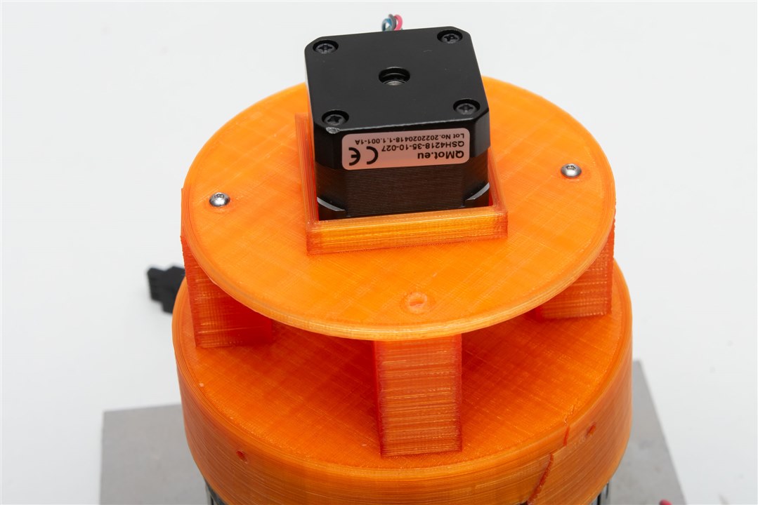
As a result, just two screws were used to secure the top plate to the hat, alongside some reaming of the screw holes to provide a bit more adjustment room. The coupling was unfortunately not very tight on the Variac side, leading to the potential for slip. Using plastic and having machine screws cut threads into it doesn’t result in much strength. This might protect the Variac from over-torque damage, but it does mean that step-to-ratio correspondence may not be maintained. The design also doesn't have a defined way to detect the end stops (e.g. by limit switches) and would instead have to either naively bump into an end stop repeatedly to guarantee a position or use StallGuard.
Attempting to run the board today, it seemed that the Landungsbrucke didn’t detect the driver. Even pressing scan didn’t work, but manually selecting it seemed to restore it to operation.

Not sure what went wrong – it was automatically detected previously. Perhaps I have a bad/broken connection somewhere.
Testing with the board shows the motor has sufficient torque to overcome the slightly stiff shaft of the Variac. The coupling does result in some motor resonances being coupled into the wiper brush assembly, which is probably not good for lifetime, but turning on StealthChop seemed to reduce some of them.
Conclusion
Well, it seems I made some rookie mistakes by not accounting for the tolerances in the top of the Variac and the 3D printer, resulting in an adapter that was just too tight, resulting in it cracking as soon as it was fitted. This could be remedied with a slight adjustment to the 3D model and a re-print. The slightly off-center part of the spindle on the Variac was not expected, but made the top plate mounting difficult. Testing seemed to show the motor to be capable enough of driving the wiper, but there is a potential for slipping with the current plastic coupling and the potential for resonances to be coupled into the wiper which might accelerate its wear.
Unfortunately, I hadn’t had any time to work on the integration of the driver control with a third-party microcontroller platform. I’m intending to use the Wiznet W5500-EVB-Pico based on the RP2040 as I’ve used with other creations, but the software will need to be ported, driver connected and tested. This time, I’m really out of time … so this will be the end of the series. At least, I’m somewhat closer to my goal, even if I did not reach it in the end.

