Table of contents

Abstract
After the unboxing the main challenge is to manage the wiring between the elements, consequently, the first project consists in the wire crimping to avoid disconnections or short circuits
Project
To increase the posibilities in the TMC5272 EVAL board I added a second stepper motor to test the interfaces. In addition, a crimper toolset is used to conditioning wires to use the manufacturer's connectors.
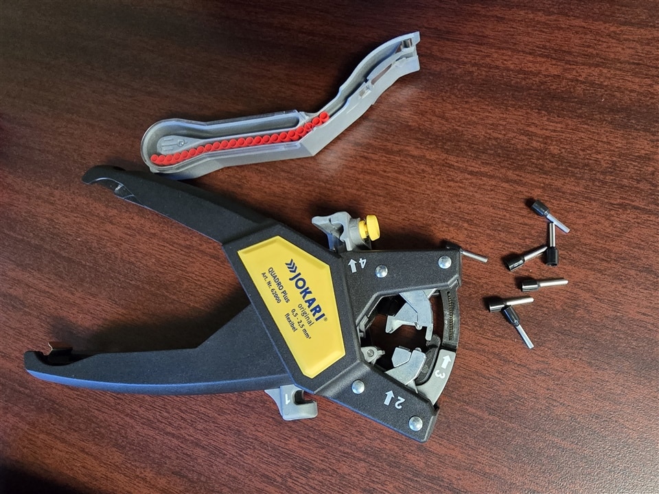
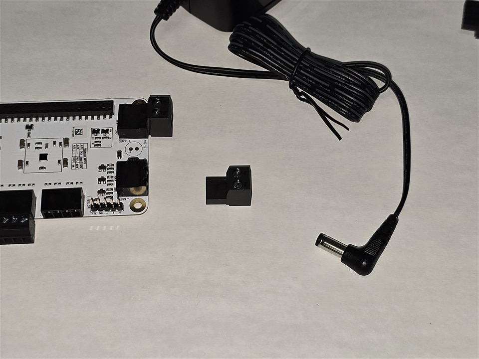
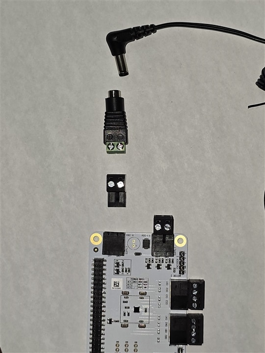
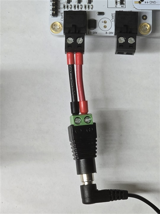
Here, the crimp tool is used to prevent damage on the provided power supply connector. A CCTV connector is used with two 18 AWG wires as a bridge between the board connector and the power connector.
| {gallery}supply connector |
|---|
|
|
|
|
 |
The second motor is a SY20STH42-0804A from pololu, which features are compared with the provided motor below
| QSH4218-35-10-027 | SY20STH42-0804A | |
| Rated Voltage (V) | 5.3 | 4.2 |
| Rated Current (A) | 1.0 | 0.8 |
| Resistance Per Phase | 5.3 (20°C) | 5.4 (25°C) |
| Inductance Per Phase | 6.6 | 1.5 |
| Holding Torque | 27(Ncm) | 300 (g.cm) |
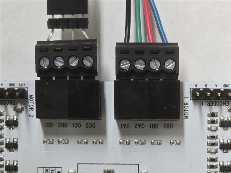
Some of the electrical features are similar, consequently, the second motor can be used in one of the channels of the board in addition to the capabilities of the power IC according to its datasheet. Since the motor I had was from a really old project and I did not want to damage its connector, a large header connector is molded to avoid inserting of more wires into the interface. Finally, the motor connections are shown below.
Here is the complete setup to be mounted, where some nylon dividers are mounted to protect the table from scratches caused by the soldered terminals.
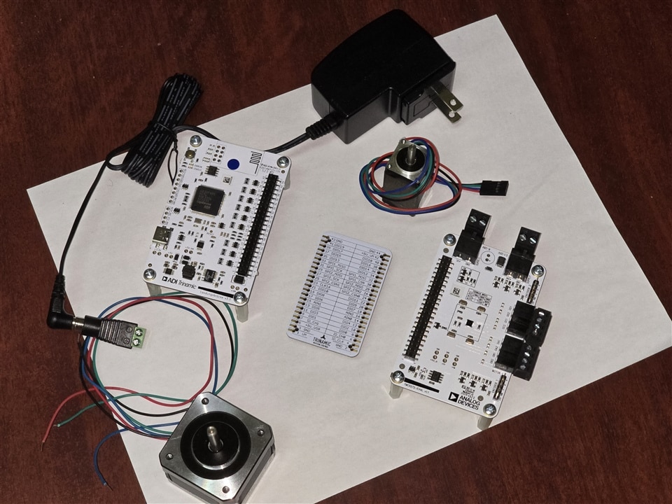
The second stage I have in mind is to create a base to mount all the boards: control, power and bridge, to avoid damage during the testing and movement. I will replace the provided power supply with a 2A from the same brand, that I used for the microscopy terminal in my last challenge.

