element14 Community
element14 Community
    Register Log In
  • Site
  • Search
  • Log In Register
  • About Us
  • Community Hub
    Community Hub
    • What's New on element14
    • Feedback and Support
    • Benefits of Membership
    • Personal Blogs
    • Members Area
    • Achievement Levels
  • Learn
    Learn
    • Ask an Expert
    • eBooks
    • element14 presents
    • Learning Center
    • Tech Spotlight
    • STEM Academy
    • Webinars, Training and Events
    • Learning Groups
  • Technologies
    Technologies
    • 3D Printing
    • FPGA
    • Industrial Automation
    • Internet of Things
    • Power & Energy
    • Sensors
    • Technology Groups
  • Challenges & Projects
    Challenges & Projects
    • Design Challenges
    • element14 presents Projects
    • Project14
    • Arduino Projects
    • Raspberry Pi Projects
    • Project Groups
  • Products
    Products
    • Arduino
    • Avnet Boards Community
    • Dev Tools
    • Manufacturers
    • Multicomp Pro
    • Product Groups
    • Raspberry Pi
    • RoadTests & Reviews
  • Store
    Store
    • Visit Your Store
    • Choose another store...
      • Europe
      •  Austria (German)
      •  Belgium (Dutch, French)
      •  Bulgaria (Bulgarian)
      •  Czech Republic (Czech)
      •  Denmark (Danish)
      •  Estonia (Estonian)
      •  Finland (Finnish)
      •  France (French)
      •  Germany (German)
      •  Hungary (Hungarian)
      •  Ireland
      •  Israel
      •  Italy (Italian)
      •  Latvia (Latvian)
      •  
      •  Lithuania (Lithuanian)
      •  Netherlands (Dutch)
      •  Norway (Norwegian)
      •  Poland (Polish)
      •  Portugal (Portuguese)
      •  Romania (Romanian)
      •  Russia (Russian)
      •  Slovakia (Slovak)
      •  Slovenia (Slovenian)
      •  Spain (Spanish)
      •  Sweden (Swedish)
      •  Switzerland(German, French)
      •  Turkey (Turkish)
      •  United Kingdom
      • Asia Pacific
      •  Australia
      •  China
      •  Hong Kong
      •  India
      •  Korea (Korean)
      •  Malaysia
      •  New Zealand
      •  Philippines
      •  Singapore
      •  Taiwan
      •  Thailand (Thai)
      • Americas
      •  Brazil (Portuguese)
      •  Canada
      •  Mexico (Spanish)
      •  United States
      Can't find the country/region you're looking for? Visit our export site or find a local distributor.
  • Translate
  • Profile
  • Settings
Start a Movement Challenge
  • Challenges & Projects
  • Design Challenges
  • Start a Movement Challenge
  • More
  • Cancel
Start a Movement Challenge
Forum Controlling Stepper Based on Flex Sensor
  • Blog
  • Forum
  • Projects
  • DC
  • Leaderboard
  • Files
  • Members
  • More
  • Cancel
  • New
Join Start a Movement Challenge to participate - click to join for free!
Actions
  • Share
  • More
  • Cancel
Forum Thread Details
  • Replies 3 replies
  • Subscribers 46 subscribers
  • Views 390 views
  • Users 0 members are here
  • design challenge
  • position control
  • flex sensor
  • trinamic motor control
  • tmc5272-eval-kit
  • tmc5272
  • start a movement
  • tmc5272 evaluation kit
Related

Controlling Stepper Based on Flex Sensor

taifur
taifur 8 months ago

I want to use a Flex sensor to control the stepper motor based on the bending of the finger. A flex sensor is a low-cost, easy-to-use variable resistor that is designed to measure the amount of deflection it experiences when bent. The sensor's resistance is lowest when it's straight or flat on the surface, increases when we bend it slowly and reaches its maximum when it's at a 90-degree angle. Due to it's size a flex sensor can be easily attached with the finger to measure the bending of the finger. 

As already said, a flex sensor is a variable resistor that varies its resistance upon bending. As the resistance of the sensor is directly proportional to the amount of bending, it's often called Flexible potentiometer. This sensor is commonly available in two sizes, the first is 2.2” and the second one is 4.5” long. I am using the 2.2 inch flex for my project. When the sensor is straight the resistance is about 25K, and when the sensor is bent the value is 69K. As flex sensor is a resistor we must convert the resistance to voltage to read it using MCU. To get a proportional voltage to the sensor we need to make a voltage divider circuit attaching a fixed resistor in series with the sensor as shown in the animated image below. Based on the bending the resistance of the sensor changes and the output voltage also changes accordingly.  

image

The image was taken from circuitdigest.com

The sensitivity of the sensor depends on the value of the fixed resistor connected with the flex sensor. For calculating the exact value for maximum sensitivity first I measured the resistance of the sensor when it is straight and when it is bent at 90 degree. Then I calculate the resistance for getting the maximum variation in the output volage using Microsoft Excel.  

image

image

image

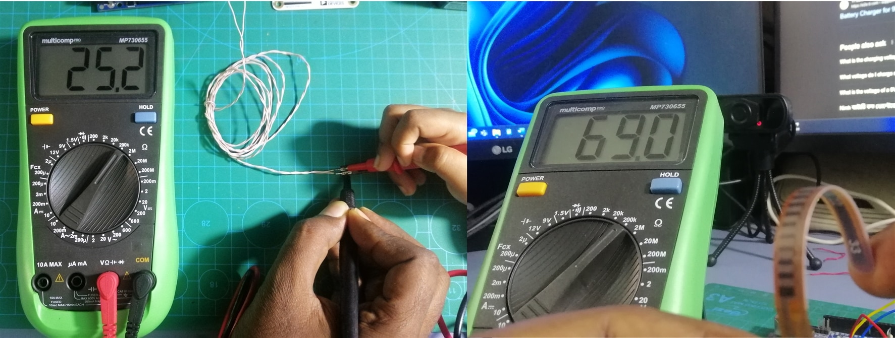
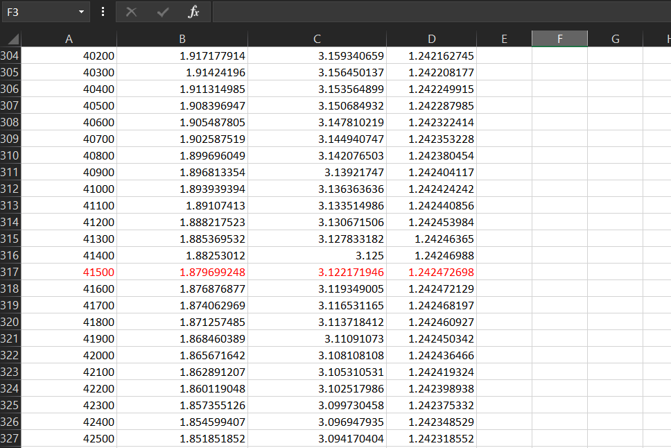
I got the maximum sensitivity for the resistance of 41.5K. So, I planned to placed a 50K trim pot and set it to 41.5K and then connect it in series with the Flex sensor to get the maximum sensitivity. But for testing I connected one 20K and one 22K resistor in series for getting an approximate output.  I used the following code for running the motor based on the bending. 

/*******************************************************************************
* Copyright © 2023 Analog Devices Inc. All Rights Reserved.
* This software is proprietary to Analog Devices, Inc. and its licensors.
*******************************************************************************/

#include <SPI.h>

extern "C" {
#include "TMC5272_register_map.h"
#include "tmc5272.h"

}

/* 
 * Arduino Pins   Eval Board Pins
 * 51 MOSI        32 SPI1_SDI
 * 50 MISO        33 SPI1_SDO
 * 52 SCK         31 SPI1_SCK
 * 53 SS          30 SPI1_CSN
 * GND            23 CLK16 -> use internal 
 * 23 DIO         19 nSleep 
 * GND            2 GND
 * +5V            5 +5V_USB
 * 27 iRefR2      35 IREF_R2
 * 29 iRefR3      36 IRREF_R3
 * 31 uartMode    20 USEL/ for uart mode it should be HIGH
 */

#define IC_ID 0

int nSleep = 23;
int iRefR2 = 27;
int iRefR3 = 29;
int uartMode = 31;

void tmc5272_readWriteSPI(uint16_t icID, uint8_t *data, size_t dataLength) {
  digitalWrite(PIN_SPI_SS, LOW);
  delayMicroseconds(10);

  for (uint32_t i = 0; i < dataLength; i++) {
    data[i] = SPI.transfer(data[i]);
    Serial.println(data[i]);
  }

  delayMicroseconds(10);
  digitalWrite(PIN_SPI_SS, HIGH);
}
int previous_value;
void setup() {
  Serial.begin(115200);

  // put your setup code here, to run once:
  pinMode(PIN_SPI_SS, OUTPUT);
  pinMode(nSleep, OUTPUT);
  pinMode(iRefR2, OUTPUT);
  pinMode(iRefR3, OUTPUT);
  pinMode(uartMode, OUTPUT);

  digitalWrite(PIN_SPI_SS, HIGH);
  digitalWrite(nSleep, LOW); // Disabling standby
  digitalWrite(iRefR2, LOW);
  digitalWrite(iRefR3, LOW);

  
  digitalWrite(uartMode, LOW);
  SPI.begin();
  SPI.beginTransaction(SPISettings(500000, MSBFIRST, SPI_MODE3));
  
  delay(10);
  
  //set resistance to 10K
  digitalWrite(iRefR2, HIGH);
  digitalWrite(iRefR3, HIGH);

  
  initMotorOne(IC_ID);
  
  tmc5272_writeRegister(IC_ID, TMC5272_RAMPMODE, 0x0); //set position mode  
  tmc5272_writeRegister(IC_ID, TMC5272_VSTART(0), 0); //set maximum valocity
  tmc5272_writeRegister(IC_ID, TMC5272_VSTOP(0), 10); //set maximum valocity
  tmc5272_writeRegister(IC_ID, TMC5272_TVMAX(0), 0); //disable jerk reduction
  tmc5272_writeRegister(IC_ID, TMC5272_AMAX(0), 50000); //set maximum acceleration
  tmc5272_writeRegister(IC_ID, TMC5272_VMAX(0), 100000); //set maximum valocity
  tmc5272_writeRegister(IC_ID, TMC5272_DMAX(0), 1000); //set maximum deacceleration
  tmc5272_writeRegister(IC_ID, TMC5272_D2(0), 1); 
  tmc5272_writeRegister(IC_ID, TMC5272_XACTUAL(0), 0); //clear actual position
 
  previous_value = analogRead(A0);
}


void loop() {
  
  int sensor_value = analogRead(A0);
  int diff = abs(sensor_value - previous_value);
  if(diff>30)
    tmc5272_writeRegister(IC_ID, TMC5272_XTARGET(0), sensor_value*10000); //set a target position
  previous_value = sensor_value;
  Serial.println(sensor_value);
  delay(15);

}

Watch the demo video below:

You don't have permission to edit metadata of this video.
Edit media
x
image
Upload Preview
image

  • Sign in to reply
  • Cancel

Top Replies

  • beacon_dave
    beacon_dave 8 months ago in reply to bidrohini +3
    https://www.analog.com/media/en/technical-documentation/user-guides/tmc5272-eval-user-manual.pdf
  • taifur
    taifur 8 months ago in reply to beacon_dave +1
    Thank you for quick reference.
Parents
  • bidrohini
    bidrohini 8 months ago

    Bhai, what is the name of the white board that you used between the Arduino and Stepper motor?

    • Cancel
    • Vote Up 0 Vote Down
    • Sign in to reply
    • Cancel
Reply
  • bidrohini
    bidrohini 8 months ago

    Bhai, what is the name of the white board that you used between the Arduino and Stepper motor?

    • Cancel
    • Vote Up 0 Vote Down
    • Sign in to reply
    • Cancel
Children
  • beacon_dave
    beacon_dave 8 months ago in reply to bidrohini

    image

    https://www.analog.com/media/en/technical-documentation/user-guides/tmc5272-eval-user-manual.pdf

    • Cancel
    • Vote Up +3 Vote Down
    • Sign in to reply
    • Cancel
  • taifur
    taifur 8 months ago in reply to beacon_dave

    Thank you for quick reference. 

    • Cancel
    • Vote Up +1 Vote Down
    • Sign in to reply
    • Cancel
element14 Community

element14 is the first online community specifically for engineers. Connect with your peers and get expert answers to your questions.

  • Members
  • Learn
  • Technologies
  • Challenges & Projects
  • Products
  • Store
  • About Us
  • Feedback & Support
  • FAQs
  • Terms of Use
  • Privacy Policy
  • Legal and Copyright Notices
  • Sitemap
  • Cookies

An Avnet Company © 2025 Premier Farnell Limited. All Rights Reserved.

Premier Farnell Ltd, registered in England and Wales (no 00876412), registered office: Farnell House, Forge Lane, Leeds LS12 2NE.

ICP 备案号 10220084.

Follow element14

  • X
  • Facebook
  • linkedin
  • YouTube