Welcome to my first project post. My project is called "AVR" and that's not named after the 8-bit microcontroller!
Why "Start a Movement"?
I decided to participate in this design challenge for a few reasons. The first was simply because it looked interesting as it involved stepper motors, something I've always wanted to employ in my own projects but never had the chance to. Such motors are great for making precise movements, being the driving force (quite literally) behind the positioning of heads in early hard drives and floppy drives, through to your humble dot-matrix printer, some CNC milling machines and even modern 3D printers. They're definitely something which can be very useful for open-loop control as well, saving the complexity of feedback control.
The next reason was simply because there seemed to be a few calls for competitors, suggesting there was a good chance to snag a kit. The prizes looked good too - I'm a big fan of eMobility solutions and I think they're a vital part of a decarbonised future.
But perhaps most importantly, I had a problem that I wanted to solve inexpensively. This is one that has been bugging me for many years and is something that you could theoretically buy your way out of, given enough money. But I didn't have that kind of money to spare.
The Problem and Concept
If you want a regulated DC power supply, you'd just grab a lab benchtop power supply or a plug-pack or perhaps even USB/USB-C PD and you'd be set. This is such a bread-and-butter requirement that we have a bread-and-butter solution to it.
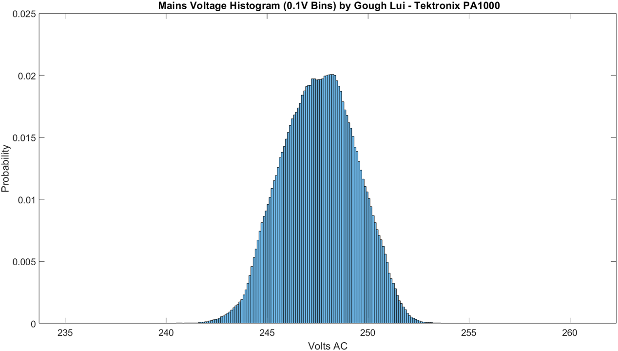
But if you want a regulated AC mains power supply, then that's a whole different kettle of fish. Your wall-socket nominal 115/230V is never quite exactly that, as loads inside the house and loads along your street can change the voltage at any time. This is simply down to how resistance in the transmission lines cause voltage drop as a function of current flow (ohms law). Aside from that, the distribution network often has tap changing transformers which can boost or buck by fixed ratios to try and bring the voltages within a band, as loads can change significantly throughout the day. For example, this is a graph I previously made of line voltage in my house across a 24 hour period:

What is nominally 230V has quite a spread. But when testing certain sorts of appliances, the voltage has a direct bearing on energy consumption, so testing with a voltage that varies would be unfair. The IEC62301 standard that has to do with standby energy qualification, for example, sets stringent voltage requirements of +/-1% of nominal for accurate testing. As a result, ordinary mains power simply cannot do (and it likely can't for other reasons, including crest factor, but we can't do much about that in this challenge).
So, I called this project "AVR", short for "Automatic Voltage Regulator". The idea would be that by taking an autotransformer (e.g. a Variac) that allows for nearly-continuous output voltage control and connecting its mechanical input shaft in such a way that it can be computer controlled, we could "close the loop" on the system by using the readings from a power analyser (e.g. the Tektronix PA1000 I previously RoadTested) in order to counteract slow mains voltage movements (e.g. up to 2 adjustments per second) and keep the output voltage within a set band, hopefully rapid enough to take out most of the influence of grid voltage variation). This is not going to help if the mains voltage has a "step" change (e.g. due to tap changer operation) but the closer to the target voltage it is, the less likely such disturbances will push the output voltage out of band. In essence, we'd be trying to keep the voltage at the set-point all the time, similar to how someone would move around to keep a basketball balanced on their finger. It probably won't be able to guarantee a +/- 1% result, but it should mean that I can run my longer mains-powered appliance tests more comfortably with less "noise" in the readings.
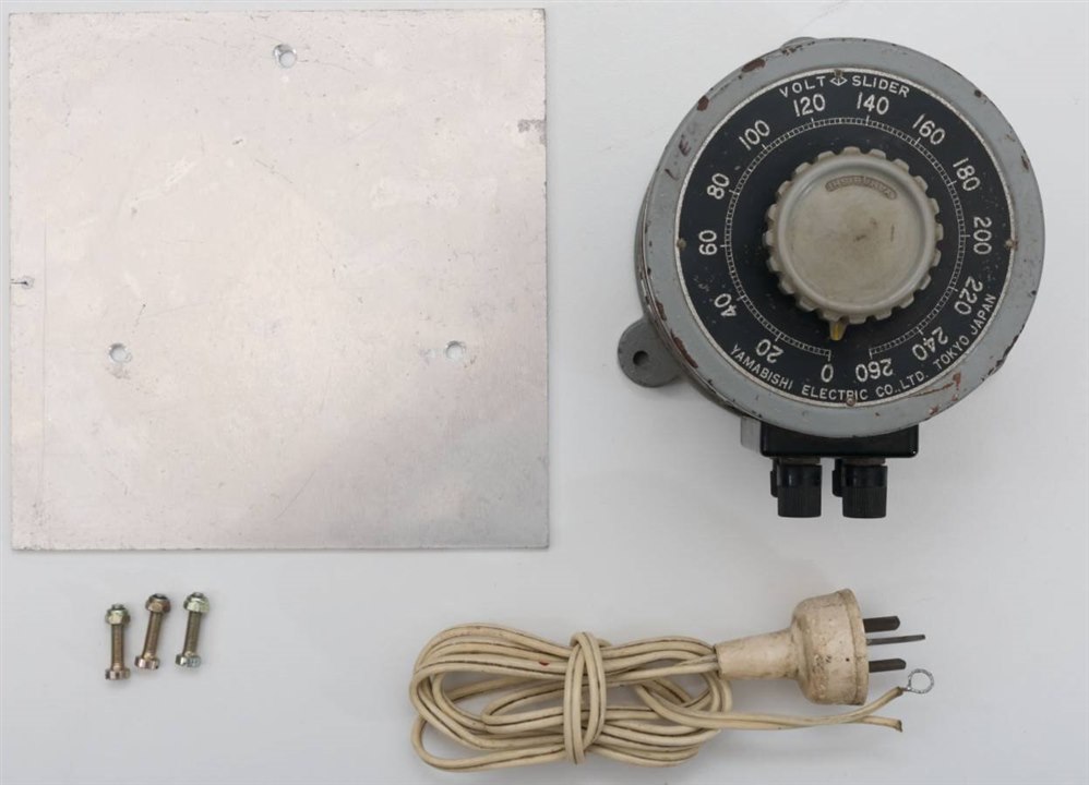
For this, we need a Variac and thankfully, I have not one but two small ones. The one I will be using for this challenge is a Yamabishi Electric (Japanese) unit I wrote about here: A Shocking Variac Made a Little Less Shocking!

My plan would be to take the knob off of the unit, design a 3D printed coupling that might take a trio of M3 screws as grub screws on both sides to couple the shafts together, all with an adapter plate that keeps the alignment of the motor and Variac body constant. Then, using the provided driver and evaluation board, I'd figure out how to get it hooked up to the computer, under computer control (USB would be fine) whereby a script could then poll my PA1000 power analyser and set appropriate adjustments on the Variac, making decisions at every step as to whether to move it or not (as the carbon brush is something that will wear down quickly if excessive unnecessary adjustments are made).
You might be thinking "Well, hold on a minute. Don't those newfangled UPSes have AVRs in them?" and you'd be right. Many line-interactive UPSes advertise the presence of AVR functionality. However, their form of AVR is made with discrete windings on a transformer, thus allowing you to "boost" or "buck" the input by a fixed percentage increment, usually something between 5-10%, causing a massive jump every time it happens. For precision AC applications, this is not ideal.
Another thought may be "Why not just use a DC to AC true sine-wave inverter as a source? They're stable, right?" and this is something I'm already doing. However, what they don't tell you is that the inverters have some higher frequency harmonic content and insufficient regulation to deal with high crest-factor loads which leads to noticeable load-modulation of the voltage. Another issue I'm also finding is that the voltages from such inverters also jump, due to temperature changes within the board and compensation for that, which are a pain whenever the inverter is not on a constant load (as every heat-up and cool-down cycle, especially with thermostatic fan) results in a voltage jump. They also seem to have an offset from the factory (230V nominal is often measured at 233V or 235V) which necessitates trimming and their limited reactive power capabilities seem to cause my power analyser to give very inaccurate power-factor readings.
Getting nice, regulated, powerful AC is something that, ideally, you should be using a synthetic mains AC source (such as these behemoths from GWInstek or Keysight) for. My pockets aren't quite so deep though ... so I'm going to try and be clever.
Conclusion
In this post, I've summarised my motivations for "starting a movement" and the project I intend to build. The whole concept of the "AVR" is to regulate mains AC voltage by allowing a mechanical autotransformer to be computer-controlled, which, when paired with a power analyser can allow for "closing the loop" forming a feedback control system that can serve to regulate the output voltage to a load within a set band on a nearly continuous basis without the jumps ordinarily associated with UPS-based AVR systems.
In the next posting, I'll be unboxing the kit and looking at its components.
P.S.
I'd like to apologise as this is an exceptionally late start to a design challenge and one that I am feeling like I am unlikely to complete. It has been about a month that I've been battling a sudden decline in my health, losing most of my central vision in one eye and losing mobility with one or both of my ankles on an on-and-off basis suffering from severe pain. This makes it a literal pain to do almost anything and really sapped away some of my motivation. Concurrently with this design challenge, I had also a period of triple-concurrent RoadTests (of which two still are in-progress), which put immense strain on the time and energy I had left.
I'm not looking for sympathy - just hoping to ensure that the community is not left empty-handed and to show that I've decided to give it a go nonetheless. While I will recover in time, it is not expected to be a quick road to recovery, expecting to take six or so months. As a result, I am intending to curtail future involvement in element14 programs until I am confident of my ability to deliver, as some of this is stress-related (likely imposed from both work and hobby). In the meantime, best of luck to my fellow challengers and I would appreciate if you would support their efforts.
