


Hello and welcome back. In this section, I get the connections ready and take a slight unexpected detour from the project.
Connecting the Motor
In the last section, I unboxed the motor which had four wire connections. This was a little new to me, as I used to recall steppers having six wires. This is because this is a bipolar stepper, as opposed to a unipolar stepper that has centre taps on each winding. For a better explanation of the differences, this page seems to be a good reference. But I suppose what it means in practice is that the driver needs to drive both coils both positive and negative, thus two H-bridges are needed at a minimum for the two windings. Thankfully, we don't have to build them discretely.
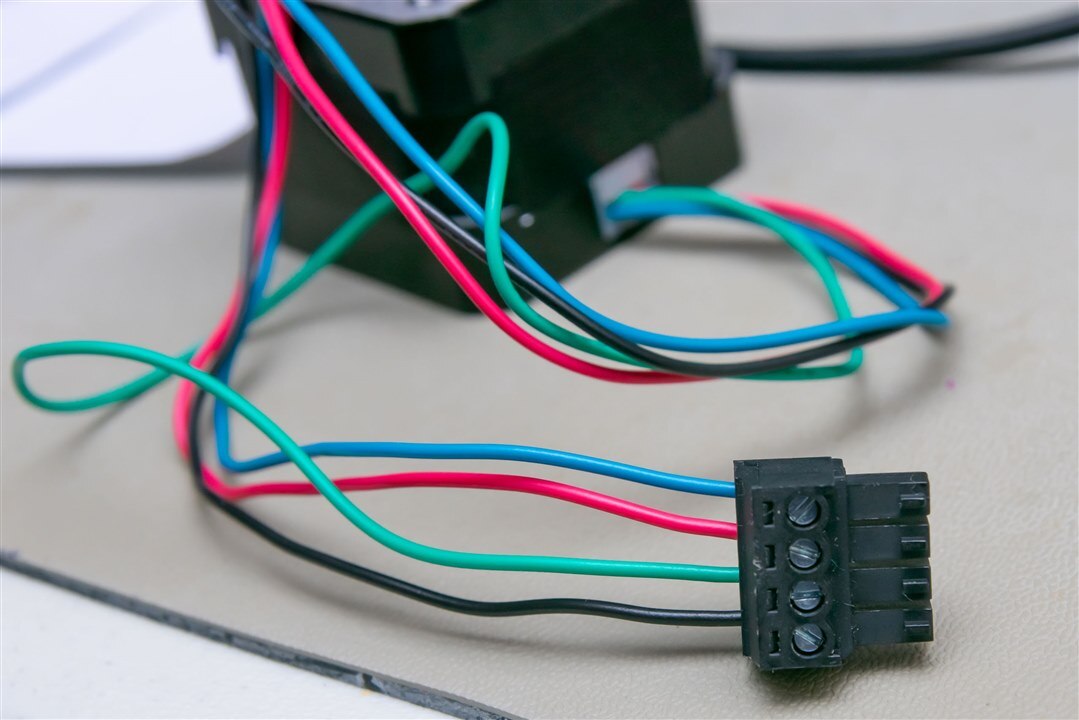
The connections on the PCB are marked OA1, OA2, OB1 and OB2. I can only surmise this to mean A phase and B phase connections 1 and 2. I don't have any real experience with these motors, but I suppose the distinction is somewhat arbitrary as to which phase is A phase and B phase, as long as the coil directions are correct. The motor itself, according to the datasheet has A+ as Black, A- as Green, B+ as Red and B- as Blue. Allocating A-phase to A and 1 as +ve, with 2 as -ve, this gives the following connection order:
Power Supply
As mentioned in the previous post, the connector on the power supply is not suitable for this kit, so it would have to be cut-off. Then, we had the interesting dilemma - what is the polarity of the wires? A quick check with the DMM appears to confirm that the supply has the striped lead as negative.
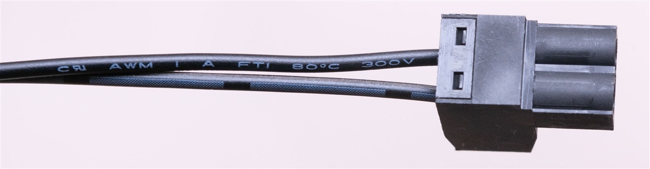
As a result, with the plug turned upside down so the lead markings are visible, I believe this to be the correct connection for the board.
I was curious as to how efficient the supply was and whether over-current protection was working. I've had some no-name power supplies blow their transistors violently when their outputs were accidentally shorted (quite a loud bang in my younger years, followed by a nice acrid-smelling smoke that I still haven't forgotten), leading to my slight reservation about using an unknown plugpack for experimentation.

The output voltage graph shows the output to be pretty decently regulated for a non-precision supply. Some power-saving mode must be present below about 100mA resulting in the downward slope of voltage initially. The adapter cut-out at about 1.34A, so a healthy margin from the 1A rating, but not too much to cause damage. The adapter was quite cool, at least on the outside, but then with just a 12W rating it isn't really dissipating all that much power given its efficiency level VI marking.
But just to be sure, I also checked the efficiency in the same test, by having my Tektronix PA1000 Power Analyser monitoring it while it was being load tested. This is based on a 230V / 50Hz (1%) input.

Of course, efficiency will be low at very low loads, but we can see the efficiency is 80%+ for 100mA or greater loads. Zooming in and doing some math ...

Efficiency mark VI requires an average efficiency of 83% for a 12W normal voltage adapter. By taking the average of all efficiency values between zero and 1A (nominal load), the computed average efficiency is 83.26%, slightly above the required 83% which manes this gets a pass. One also has to consider the fact I'm not an accredited test lab, not controlling for temperature/humidity or calibrating my equipment regularly, so this is an excellent result nonetheless.
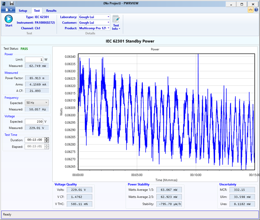
Standby power is required to be below 100mW and according to PWRVIEW, it measured 62.923mW so that's also a pass. Nothing to complain about here! Of course, there are other tests I could run, such as ripple and noise, or insulation resistance testing, but I think the above was already diversion enough. On the upside, at least it seems the Multicomp Pro supply is decent in its fresh-state and suitable for running the kit (with its input accommodating 8-20V). How well it lasts in the long run is something that only time can tell.
However, it is probably not the ideal supply for the kit - according to the stepper motor datasheet, the ideal value for a chopper-based driver is somewhere between 4 to 22 x Ucoilnom which is 5.3V for my motor. This suggests a 24V supply may be better (using common voltages). The problem is that the single voltage input for the kit is limited to 20V, so unless you have two supplies, then it's going to be out of range. On the other hand, perhaps 20V isn't quite as hard to get - USB-C PD can supply it, given a >45W supply, but even that is a bit marginal. I guess the only limitation given the power supply is a limitation in motor velocity or torque attainable.
Conclusion
In this part, I've been able to make the necessary connections (correctly, I hope) to enable me to set up the board with a computer. I also took a nice time testing out the included power supply which appears to be all good. The power supply may not be perfectly ideal for the application (the datasheet suggests 4-22x Ucoilnom which is 5.3V) for maximum velocity, but it should still work. Perhaps a 24V power supply would have been a better choice but the single-supply input on the evaluation board is designed only for up to 20V which is not all that common of a voltage. Then again, with USB-C PD, perhaps it's not as uncommon as it once was either ...
The next step is to hook it all up to a computer using a USB-C cable, install TMCL-IDE, update the firmware (if necessary), plug in the motor and power and see whether I can get it to move.
