In my project, I am using a flex sensor for detecting the bending of the finger to control the foot pedal. A flex sensor is a variable resistor and we need to convert the resistor value to a proportional voltage output to read it using a microcontroller. We usually make a voltage divider circuit to get proportional voltage from the sensor. In one of my previous writings, I calculated the value of the series resistor to get maximum sensitivity from the flex sensor. The value was around 42K and I connected one 20K and one 22K resistors in series to get 42K resistance. The sensor connection is shown in the image below.


Without using any external PCB I directly soldered the resistors and flex sensor's terminal to the Arduino board as shown in the image above.
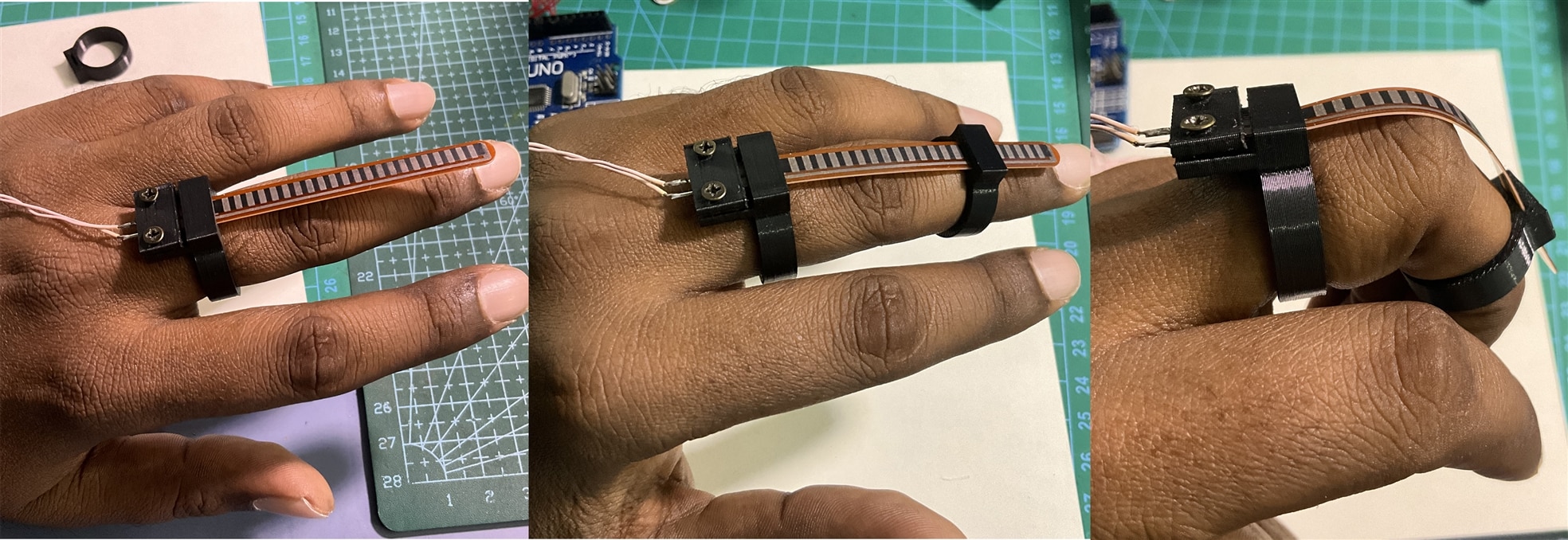
I added a long flexible wire to the flex sensor so that it can be bent from a distance. The flex sensor will be worn on a finger and the sensor should be easily bent and straight without any issue. To make the process stable and comfortable I designed two 3D printed rings with small holes for the sensor. The bigger ring will be worn first and the sensor's lead side is tightly attached to the ring using two screws.

The wearing process of the sensor is shown in the following images. The sensor can move easily inside the top ring but it can not get out from the ring.


The video in action:
All the 3D design files are attached below.
