element14 Community
element14 Community
    Register Log In
  • Site
  • Search
  • Log In Register
  • About Us
  • Community Hub
    Community Hub
    • What's New on element14
    • Feedback and Support
    • Benefits of Membership
    • Personal Blogs
    • Members Area
    • Achievement Levels
  • Learn
    Learn
    • Ask an Expert
    • eBooks
    • element14 presents
    • Learning Center
    • Tech Spotlight
    • STEM Academy
    • Webinars, Training and Events
    • Learning Groups
  • Technologies
    Technologies
    • 3D Printing
    • FPGA
    • Industrial Automation
    • Internet of Things
    • Power & Energy
    • Sensors
    • Technology Groups
  • Challenges & Projects
    Challenges & Projects
    • Design Challenges
    • element14 presents Projects
    • Project14
    • Arduino Projects
    • Raspberry Pi Projects
    • Project Groups
  • Products
    Products
    • Arduino
    • Avnet Boards Community
    • Dev Tools
    • Manufacturers
    • Multicomp Pro
    • Product Groups
    • Raspberry Pi
    • RoadTests & Reviews
  • Store
    Store
    • Visit Your Store
    • Choose another store...
      • Europe
      •  Austria (German)
      •  Belgium (Dutch, French)
      •  Bulgaria (Bulgarian)
      •  Czech Republic (Czech)
      •  Denmark (Danish)
      •  Estonia (Estonian)
      •  Finland (Finnish)
      •  France (French)
      •  Germany (German)
      •  Hungary (Hungarian)
      •  Ireland
      •  Israel
      •  Italy (Italian)
      •  Latvia (Latvian)
      •  
      •  Lithuania (Lithuanian)
      •  Netherlands (Dutch)
      •  Norway (Norwegian)
      •  Poland (Polish)
      •  Portugal (Portuguese)
      •  Romania (Romanian)
      •  Russia (Russian)
      •  Slovakia (Slovak)
      •  Slovenia (Slovenian)
      •  Spain (Spanish)
      •  Sweden (Swedish)
      •  Switzerland(German, French)
      •  Turkey (Turkish)
      •  United Kingdom
      • Asia Pacific
      •  Australia
      •  China
      •  Hong Kong
      •  India
      •  Korea (Korean)
      •  Malaysia
      •  New Zealand
      •  Philippines
      •  Singapore
      •  Taiwan
      •  Thailand (Thai)
      • Americas
      •  Brazil (Portuguese)
      •  Canada
      •  Mexico (Spanish)
      •  United States
      Can't find the country/region you're looking for? Visit our export site or find a local distributor.
  • Translate
  • Profile
  • Settings
Sudden Impact Wearables Design Challenge
  • Challenges & Projects
  • Design Challenges
  • Sudden Impact Wearables Design Challenge
  • More
  • Cancel
Sudden Impact Wearables Design Challenge
Blog Part1.3 ECG output of AD8232
  • Blog
  • Forum
  • Documents
  • Polls
  • Files
  • Events
  • Mentions
  • Sub-Groups
  • Tags
  • More
  • Cancel
  • New
  • Share
  • More
  • Cancel
Group Actions
  • Group RSS
  • More
  • Cancel
Engagement
  • Author Author: sunnyiut
  • Date Created: 17 Mar 2015 6:28 PM Date Created
  • Views 4004 views
  • Likes 4 likes
  • Comments 11 comments
  • sudden_impact
  • ad8232-evalz
  • total_player
Related
Recommended

Part1.3 ECG output of AD8232

sunnyiut
sunnyiut
17 Mar 2015

Posted by Md. Kamrul Hussain March 17, 2015

Title: Total Player Monitoring

By: Md. Kamrul Hussain

Project Category: Design Challenge

Project Name: Sudden Impact Wearables Design Challenge

Blog post: 04


Intro:

It’s my fourth blog post in the Sudden Impact Wearables Design Challenge. Last couple of months was a bit hard for me. Got stuck with other stuffs and could not manage enough time to carry on this deign challenge. However, I am back again.

In this blog post I’ll be presenting the analysis of the ECG signals I have got from the Analog Front End, AD8232.


Setup:

Image of the full setup -                                                    Analog Front End AD8232 and Electrodes -

imageimage


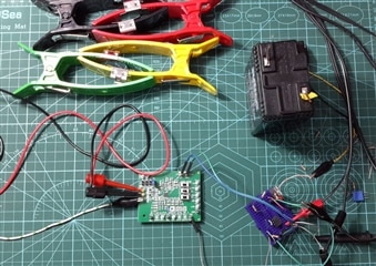
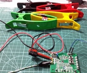
Conventional Ag-AgCl electrodes were used for this experiment.


Supply and Isolation -


image

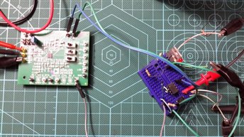
The Breadboard circuit is to provide the required 3.3v supply from a 6v battery and the opto isolation circuitry to observe the signal onto a scope without connecting it’s GND with the AFE. This keeps the signal clean from noise and also provides the minimum medical safety.
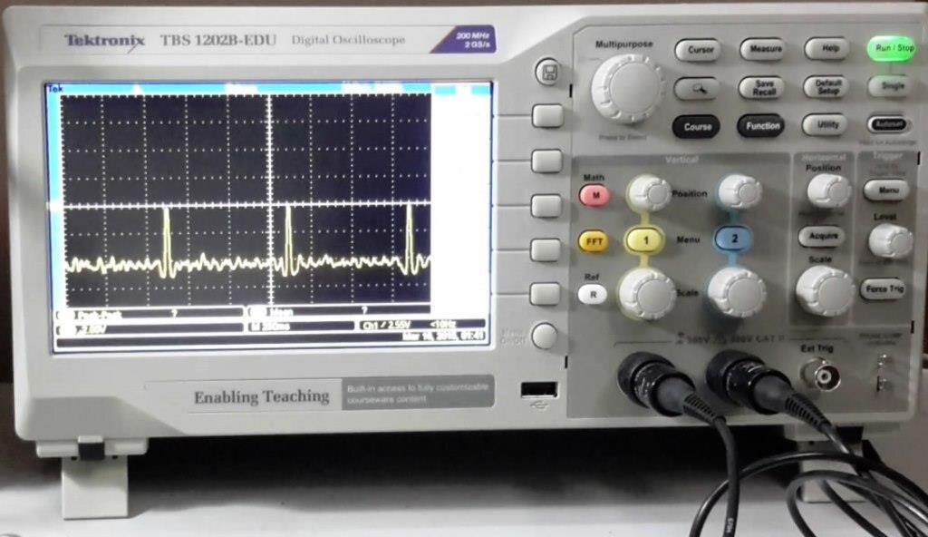
 

ECG output:


image


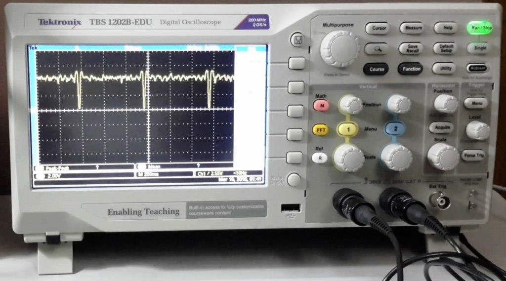
The captured ECG signal from AD8232 displayed on TBS1202B scope with 250msec time scale. The signal was inverted due to the use of opto isolator. By inverting the scope input I got the conventional output.
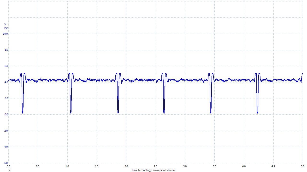
image


Output analysis:

The output of the AD8232 was taken as the Fast Response switch was disabled.

image


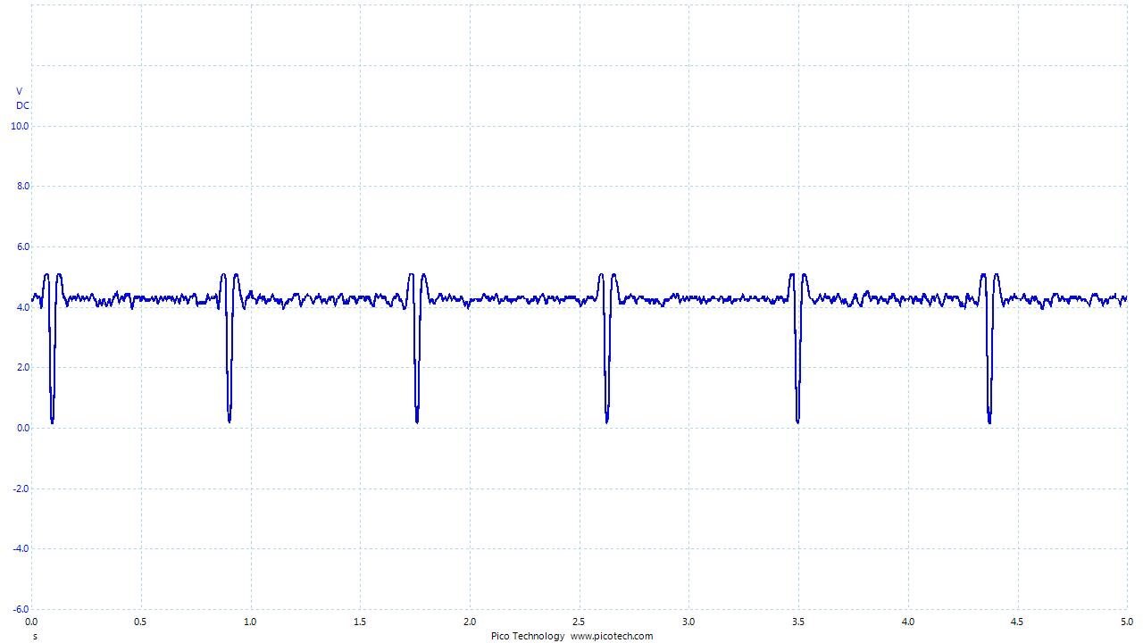
With enabling the Fast response switch I got an output almost similar to the previous one.

image


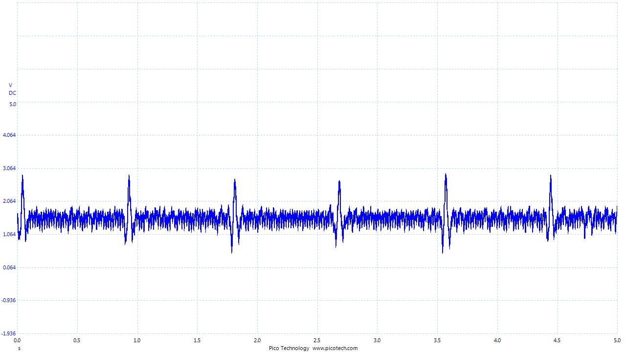
If I compare the output of AD8232, with the primary AFE designed by me then I can observe some differences.

image


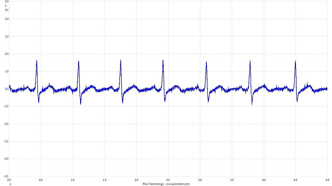
This was the output of the primary AFE. It shows that the AD8232 is missing detail information in the signal. Like the P-wave is flatten and the whole T-wave is superimposed with the 50Hz noise.


May be that’s because of the filter bandwidth. In my design I had captured in between a range of 0.3Hz to 159Hz where AD8232 limits the low pass far below 50Hz to get rid of common noise. However, this won’t be necessary as it’s not for diagnostic purpose. I just need to get the heart rate with single LEAD ECG, so it’s pretty good enough. Moreover, AD8232 produces a better, sharp QRS complex which will be more helpful.


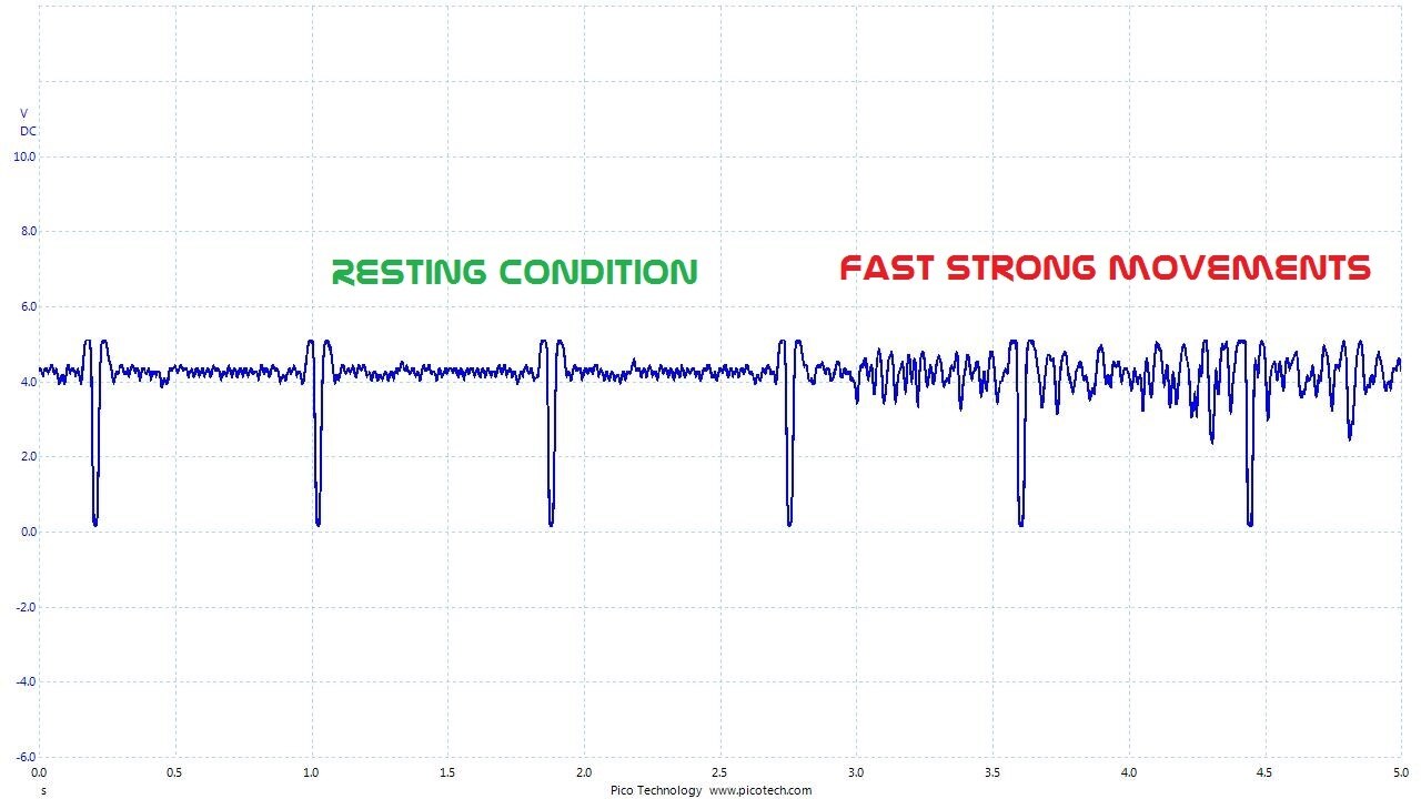
However, AD8232 responded effectively for removing motion artifacts. For general movement, it maintains the output signal pretty good. But for fast strong movements or contraction of the muscle the signal gets distorted. I have to check it's performance over motion artifacts once again after mounting it on human body.


image

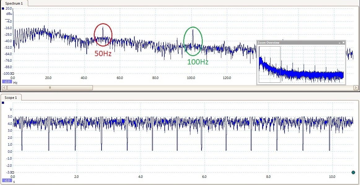
All the outputs of the AD8232 is presented inversely because of the opto-isolator. The original output without isolator looks like below, where the 50Hz noise is added from oscilloscope.


image


Spectrum view:

image


Fast response:

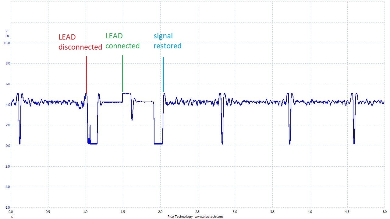
With fast response enabled, the output was restored almost immediately after reconnecting the LEAD. With fast response disabled, the output becomes steady after about 0.5 to 1.5 seconds.

image


Shutdown:

The shutdown feature works perfectly.

imageimage

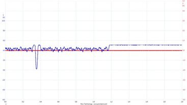
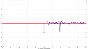
     image: Shutdown is turned on.                                        image: Signal restored after shutdown is turned off
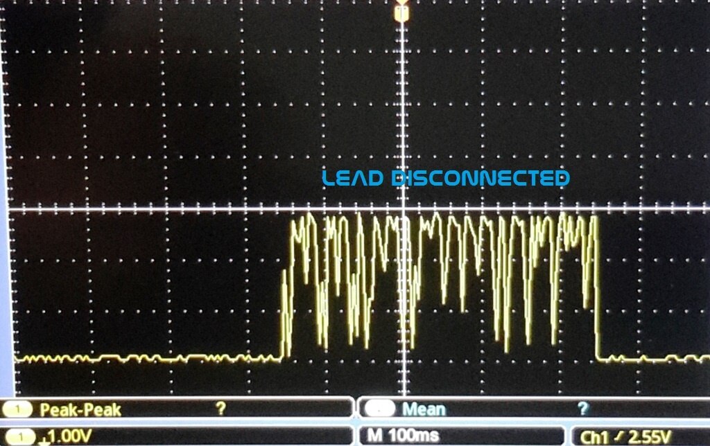
 

LEAD off detection:

  Unfortunately, the LOD+/- didn’t perform as I thought. I placed the switch into DC position and removed one LEAD. I was expecting something like a digital high/low output swing. But when the LEAD was taken off the LOD output started oscillating.


image

You don't have permission to edit metadata of this video.
Edit media
x
image
Upload Preview
image


In my next blog I’ll try to post the full circuit for detecting the heart rate from the ECG signal.

  • Sign in to reply

Top Comments

  • sunnyiut
    sunnyiut over 10 years ago in reply to DAB +1
    Thank you DAB, Yeah - I am using battery here indeed. But I still need the isolator, because if I connect the oscilloscope GND into the AFE board, 50 Hz noise will be added. However, I won't need the isolator…
  • ravi_butani
    ravi_butani over 10 years ago +1
    Excellent blog... very informative....
  • teprojects1
    teprojects1 over 8 years ago

    I would Like to add More on TL072 here you will found some basic and datasheet to understand it more.


    Teprojects.1
    • Cancel
    • Vote Up 0 Vote Down
    • Sign in to reply
    • More
    • Cancel
  • kas.lewis
    kas.lewis over 10 years ago in reply to sunnyiut

    Thank you for the helpful information


    Kas

    • Cancel
    • Vote Up 0 Vote Down
    • Sign in to reply
    • More
    • Cancel
  • sunnyiut
    sunnyiut over 10 years ago in reply to kas.lewis

    hello Kas,

    here is the design for isolation.

    image

    The upper design will be the best to try, whereas I have used the lower one [a simplified version] for my experiment.

    Opto-isolator [Upper design]:

    The main concept is to observe the signal without connecting the ground of the oscilloscope into the main AFE, as the 50/60 Hz noise can get into the system.

    A general purpose opto coupler [i have used P521] can help to create the barrier.

    The Upper design is kind of a good practice [i hope]. In this case, the RV_ISO can be tuned to shift the output signal from AD8232, into a suitable level to get the full dynamic range of the optocoupler. Let's say the RV_ISO gives a fixed DC voltage. U2:A will buffer that voltage. U2:B will be used to mix the signal with the shifted voltage. It means the incoming ECG signal will be shifted with a base line of that fixed voltage. So the LED of the Optocoupler will remain on for all the time but the intensity will vary with the variation of the incoming ECG signal. So, the phototransistor's output current will also vary with the signal and due to the pull up resistance [R_PULLUP], we'll get a variable voltage output representing the original ECG signal. R_PULLUP can be varied to change the gain of the system.


    Simplified OPTO-ISOLATOR:

    In the upper design, I have used a dual opamp, TL072. It has to be powered by dual supply. But the AFE is running on single supply [3.3v] and it has to be powered by battery to get rid of common 50Hz noise. The interesting point is that, the AD8232 board has internal reference voltage generator. It divides the 3.3v into +/- 1.5v and the reference voltage can be accessed through TP19 terminal.

    So, the TL 072 opamp can be powered using the 0 - 3.3v supply as dual supply [+/- 1.5v] with the reference output of AD8232.

    Now, that means the signal is already shifted to 1.5v [DC] respective of 0v [-ve terminal of the battery supply]. And also if you see the circuit diagram of AD8232 board, the output is directly coming out of the internal amp used as low pass filter. It means the output has capability to provide enough current to drive the Opto coupler. Therefore, I have used the simplified design [lower part], where the output drives the opto coupler directly. U can vary the R_ISO to fit the ECG signal into the dynamic range of the opto-coupler and R_PULLUP can be varied to change the gain of the system.


    ** another important stuff is that - opto coupler gives the minimum health safety from mains power supply. if we connect the gnd of the oscilloscope into the AFE board it cannot provide the isolation from mains supply. Though it's not a problem in general/normal case, but in abnormal/faulty case it becomes a life risk as the maximum safe current limit through human heart is only 10uA image.


    This is what I can explain from my limited resource. Please let me know if u have any confusion and best of luck with your try.

    thank u

    • Cancel
    • Vote Up 0 Vote Down
    • Sign in to reply
    • More
    • Cancel
  • kas.lewis
    kas.lewis over 10 years ago

    Hello,


    Awesome blog entry and very informative, I really like how everyone in the challenge is open to sharing their tricks and helping eachother image On that note, I was wondering about your optoisolator circuit, if you could explain more about that setup as I would really like to try get that part of my system working or at least get it working on the scope.


    Thanks

    Kas

    • Cancel
    • Vote Up 0 Vote Down
    • Sign in to reply
    • More
    • Cancel
  • sunnyiut
    sunnyiut over 10 years ago in reply to ravi_butani

    for large and fast movements the signal also gets distorted for me. but I would like to work on it. so, I'll try to find the optimum placements of electrodes and beat detection algorithm.

    let's hope for the best.

    on the other hand, optical pulse sensor [plethysmograph] has the same limitation. It also gets distorted due to motion artifact. However, i'll try to check the performance of plethysmograph too, if i get enough time. I have wasted so much time... I am afraid that I may not be able to implement all the features I had planned.

    however, best of luck with your second try. hopefully, this time you will find it better. please let us know about your findings.

    -thank you.

    • Cancel
    • Vote Up 0 Vote Down
    • Sign in to reply
    • More
    • Cancel
>
element14 Community

element14 is the first online community specifically for engineers. Connect with your peers and get expert answers to your questions.

  • Members
  • Learn
  • Technologies
  • Challenges & Projects
  • Products
  • Store
  • About Us
  • Feedback & Support
  • FAQs
  • Terms of Use
  • Privacy Policy
  • Legal and Copyright Notices
  • Sitemap
  • Cookies

An Avnet Company © 2025 Premier Farnell Limited. All Rights Reserved.

Premier Farnell Ltd, registered in England and Wales (no 00876412), registered office: Farnell House, Forge Lane, Leeds LS12 2NE.

ICP 备案号 10220084.

Follow element14

  • X
  • Facebook
  • linkedin
  • YouTube