


Title: Total Player Monitoring
By: Md. Kamrul Hussain
Project Category: Design Challenge
Project Name: Sudden Impact Wearables Design Challenge
Blog post: 08
Intro:
This is a short update on detecting head impact injury using ADXL377 3 axis accelerometer. The goal is to detect potential concussion type collisions during a game.
Components:
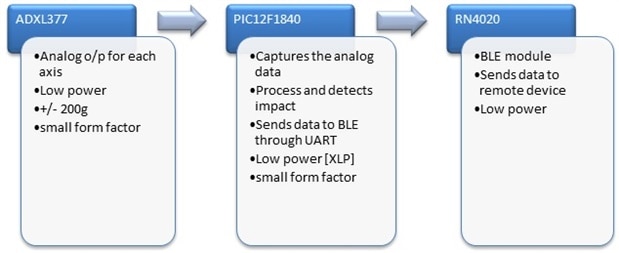
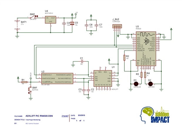
The sensor provides analog outputs for individual 3-axis which can be processed by PIC12F1840 microcontroller to detect the impact due to collisions. PIC12F1840 is a small [8 pins only], cost effective and low power Microcontroller with all the functions needed for this design. It has 4 channel 10 bit ADC for capturing analog data from ADXL377. The UART module is used to communicate with the BLE [RN4020]. It has internal oscillator up to 32MHz and XLP version ensures low power consumption [34uA @ 1MHz]. So, the full impact detection module can be constructed in a small circuit board and can be powered for long time without changing the Battery. This is necessary because I am going to mount it on a HEAD BAND, so it should be small and have long battery support.
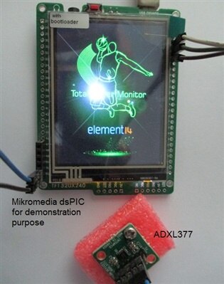
In this short blog post I am just uploading the images of experimenting with the ADXL377 module. For demonstration purpose I am using Mikromedia dsPIC board from Mikroelektronika, to display the output of the ADXL377.
Setup:
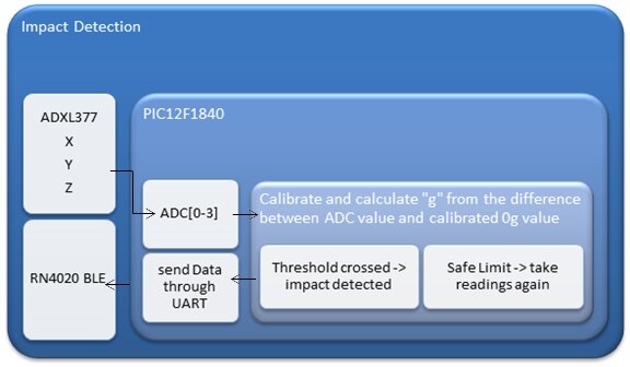
This setup is pretty straight forward. If the ADC reading exceeds a certain value then send impact data through BLE. Here, I'll just display the data on the TFT screen for demonstration.
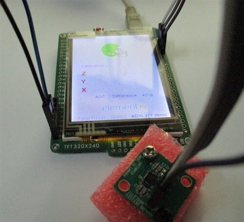
Calibration:
After powering up the ADXL377 sensor, it has to be calibrated for 0g in each of the axis. In general, it produces around Vs/2 at 0g and varies up Vs and down to 0v respectively for positive and negative variation of acceleration value. It means, for 3.3v supply the 0g value would be around 1.65v or 512 ADC value. So, before taking actual measurements the controller takes 20 readings for each axis and averages the readings to get the ADC value for 0g state.
Output at stationary condition:
The calibrated values for each axis slightly vary from expected value [512]. It depends on the position of the sensor and the surface flatness where the sensor is placed.
For calculating the g value, I am simply counting the half value of the difference between ADC and calibrated value.
Vs = 3.3v
ADC resolution = 10bit -> 1024
So, each step = 3.2226 mV
Therefore, 2 steps = 6.445 mV ~= typical output voltage change of ADXL377 for per g variation.

Output at low impact:
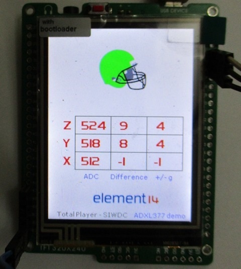
By shaking the sensor with hand or hitting with a rubber pad it gives a low impact and the output stays below 10g. The helmet icon stays in green [lime green indeed]. But if the sensor experiences a free fall or hit by the rubber pad directly on to the sensor surface, the z-axis shows huge variation !!!!
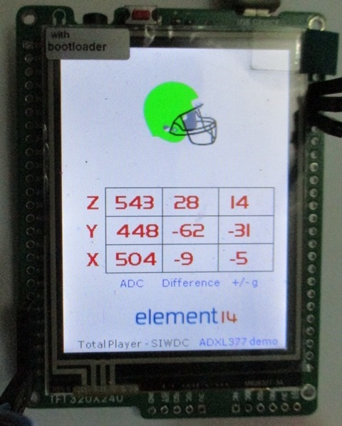
Output at high impact:

For higher impact the helmet has changed its color into RED, which indicates an impact detection. I have placed a threshold value of 12g just for demonstration purpose.
But I have got unexpected output / behavior couple of times, where I hit the sensor not so hard but it showed higher values [no way I can produce -31g with that weak hit]  and still the helmet didn't change the color [stays green]!!!
It's weird.... I think it's a bug in my coding, but it's a simple code and if the sensor somehow shows higher values, the helmet has to change its color???? So, I'll try to figure it out later on. Hopefully it's a silly mistake 
Circuit Diagram:
next step - I'll make the board and mount it into a Head Band to check out the performance.
Top Comments