


Title: Total Player Monitoring
By: Md. Kamrul Hussain
Project Category: Design Challenge
Project Name: Sudden Impact Wearables Design Challenge
Blog post: 09
Intro:
It's an update on the temperature sensor ADT7320. It's a part of the module 04 [central hub]. This sensor will be placed on the back of the wrist and will be mounted along with the central hub. In this blog post I'll demonstrate the outputs of the sensor with different configuration and simulate a visual indication of crossing the temperature limits.
But before that I would like to recall my proposal on the basic structure of the 'central hub' and the other modules belong to it.
Central Hub:
According to my proposal, the central hub will communicate with all the modules through Bluetooth and it will maintain a long range communication bridge [Using BlueGiga WT41] with the remote device held by the trainer. The hub itself will accommodate a few other modules and will be placed on the back of the wrist.
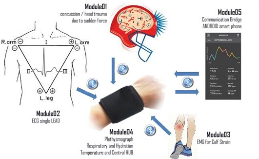
Sub-modules:
- Temperature Sensor
- Impedance measurement for detecting Dehydration
- Photoplethysmograph for SPO2
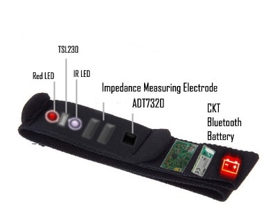
proposed model for mounting the module 04 hardware in a wrist band ->
Today I am presenting the first part of this module -> Temperature Sensor. I have done some hardware work and preliminary design of other two parts. But none of them are completed yet. However, I'll carry on according to my plan step by step, but shall try to post updates on the other two parts [impedance and plethysmograph] within the deadline of the submission. So, that I'll be able to give a generous idea of how much work has been done or partially done by me so far.
ADT7320 Temperature Sensor:
Range -> -20'C to 105'C at 3.3v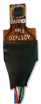
Resolution -> 0.0078'C at 16bit
Communication -> SPI mode3
Benefits ->
- different mode selection for lower power operation
- wide operating range
- easy implementation as no calibration is needed
- hardware capability of generating interrupts
Protocol structure:
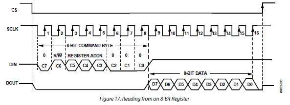
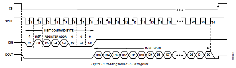
ADT7320 operates in Mode3, where the idle state = clk high and data sampled at active to inactive [low to high rising] state.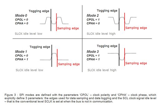
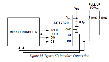
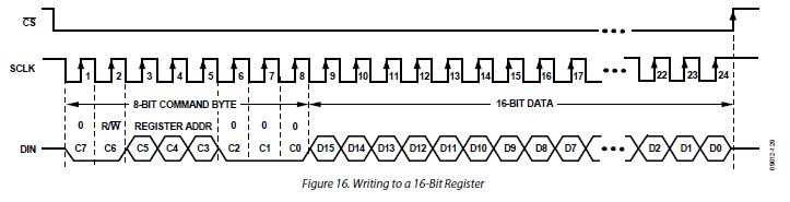
ADT7320 has both 8bit and 16 bit reading and writing structure depending on the size of the target register. But for every read or write operation, 8-bit command byte has to be written at first.
I have shown the writing and reading structure from the datasheet at the end of the blog.
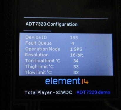
Configuration:
I have experimented with both the 13-bit and 16-bit data structure with continuous and 1SPS operating mode and also changed the temperature limits from default value to get the desired interrupts. Finally I have chosen the following configuration for my design ->
- resolution -> both 13 and 16-bit depending on the demand
- fault queue -> 4 consecutive faults to generate an interrupt
- operation mode -> 1SPS, one sample per second to save the power. It takes only 46uA at 3.3v for 60msec and stays at stand by for 940msec. The captured data can be read any time from the buffer even in stand by mode. So, it saves a lot of power consumption as the body temperature does not change at once suddenly and we don't need the continuous data conversion.
- interrupts -> just for demonstration purpose
- critical value = 34'C
- high limit = 33'C
- low limit = 32'C
Calculation of Temperature:

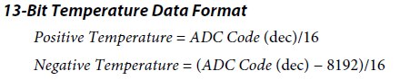
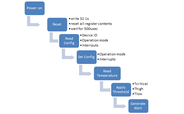
Steps:
Hardware:
I am using Mikromedia board for demonstration. Unlike previous cases, this time I am going to use the dsPIC33EP microcontroller of Mikromedia board for this module. Because, I have other sub-modules like impedance measurement and plethysmograph, where the DSP will be needed to process the signals.
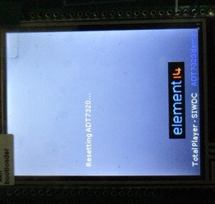
Step 01 - Reset:
After powering up the first step is to reset the SPI interface and reset all the register contents which ensures that the sensor is ready for stable performance.
To do that logic high [1] has been sent into DIN line of the sensor for 32 times.
device setup reset ADT7320

Step 02 - Read Configuration:
After resetting the sensor it's better to read the configuration to see whether the operation mode is in expected form.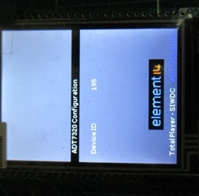
First to check the device ID.
command byte frame for reading the device id :
01011000 -> 0x58 hex
C7 | C6 | C5 | C4 | C3 | C2 | C1 | C1 |
0 | R/*W | Register address | 0 | 0 | 0 | ||
0 | 1 | 0 | 1 | 1 | 0 | 0 | 0 |
IDT7320 responded with 195 = 0xC3 hex, which was expected.
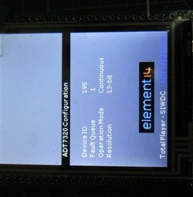
Then the 'Configuration' register gives the operation mode for ADT7320.
command byte frame for reading the configuration :
01001000 -> 0x48 hex
C7 | C6 | C5 | C4 | C3 | C2 | C1 | C1 |
0 | R/W | Register address | 0 | 0 | 0 | ||
0 | 1 | 0 | 0 | 1 | 0 | 0 | 0 |
The ADT3720 was running in default mode with 'continuous' data conversion at 13-bit resolution.
The Fault Queue was single fault to generate interrupt.
After that, the Temperature limits for interrupt generation were verified.
command byte for reading the interrupts :
T(critical) = 0x60 hex
T(high) = 0x 70 hex
T(low) = 0x78 hex
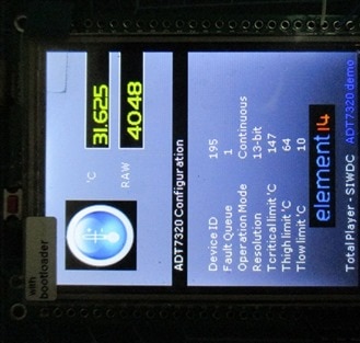
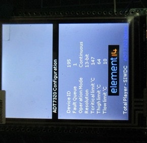
IDT3720 gave the default value of 147'C, 64'C and 10'C respectively
The right side image represents an example of reading temperature at default operating mode.
Step 03 - Set Configuration:
By reading the configuration I came to know that the sensor is running in 'Continuous' mode with 13-bit resolution. Now as I want to use the sensor in 16-bit 1sample per second for more precise output and less power consumption, I need to change the configuration register. I would like to change the temperature interrupt limits as well for demonstration purpose.
frames for new configuration register ->
command byte = 00001000 = 0x08 hex
C7 | C6 | C5 | C4 | C3 | C2 | C1 | C1 |
0 | R/W | Register address | 0 | 0 | 0 | ||
0 | 0 | 0 | 0 | 1 | 0 | 0 | 0 |
write to configuration register = 11000011 = 0xC3 hex
C7 | C6 | C5 | C4 | C3 | C2 | C1 | C1 |
1 | 1 | 0 | 0 | 0 | 0 | 1 | 1 |
For Interrupts -> command byte register value to write value
T(critical) 0x20 hex 0x1100 hex 34'C
T(high) 0x30 hex 0x1080 hex 33'C
T(low) 0x38 hex 0x1000 hex 32'C
Step 04 - Read Temperature:
frames for reading temperature ->
command byte = 01010000 = 0x50 hex
C7 | C6 | C5 | C4 | C3 | C2 | C1 | C1 |
0 | R/W | Register address | 0 | 0 | 0 | ||
0 | 1 | 0 | 1 | 0 | 0 | 0 | 0 |
Outputs at different temperatures:
For demonstration purpose I have used a very small range of temperature limits.
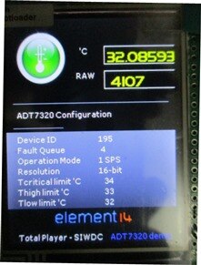
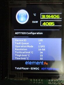
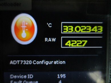
Normal Temperature [32 -33 'C] -> The thermometer ICON stays green to indicate normal temperature.

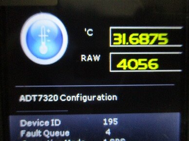
Low Temperature [ < 32 'C] -> The thermometer ICON becomes blue to indicate low temperature.
High Temperature [ 33 - 34 'C] -> The thermometer ICON becomes orange to indicate higher temperature.

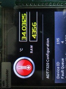
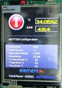
Critically High Temperature [ > 34 'C ] -> The thermometer ICON becomes red.
So, this is the Temperature Sensor part of Module 04 - central hub. On my next blog I'll post about 'Detection of Dehydration using Impedance Measurement' [partial work - whatever I have done so far].
**these are the writing and reading structure of IDT7320 SPI protocol for both 8 and 16 bits taken from the datasheet.
Writing structure ->
8 bit

16 bit
Reading Structure ->
8 bit
16 bit
Top Comments
-

DAB
-
Cancel
-
Vote Up
+1
Vote Down
-
-
Sign in to reply
-
More
-
Cancel
Comment-

DAB
-
Cancel
-
Vote Up
+1
Vote Down
-
-
Sign in to reply
-
More
-
Cancel
Children