element14 Community
element14 Community
    Register Log In
  • Site
  • Search
  • Log In Register
  • About Us
  • Community Hub
    Community Hub
    • What's New on element14
    • Feedback and Support
    • Benefits of Membership
    • Personal Blogs
    • Members Area
    • Achievement Levels
  • Learn
    Learn
    • Ask an Expert
    • eBooks
    • element14 presents
    • Learning Center
    • Tech Spotlight
    • STEM Academy
    • Webinars, Training and Events
    • Learning Groups
  • Technologies
    Technologies
    • 3D Printing
    • FPGA
    • Industrial Automation
    • Internet of Things
    • Power & Energy
    • Sensors
    • Technology Groups
  • Challenges & Projects
    Challenges & Projects
    • Design Challenges
    • element14 presents Projects
    • Project14
    • Arduino Projects
    • Raspberry Pi Projects
    • Project Groups
  • Products
    Products
    • Arduino
    • Avnet Boards Community
    • Dev Tools
    • Manufacturers
    • Multicomp Pro
    • Product Groups
    • Raspberry Pi
    • RoadTests & Reviews
  • Store
    Store
    • Visit Your Store
    • Choose another store...
      • Europe
      •  Austria (German)
      •  Belgium (Dutch, French)
      •  Bulgaria (Bulgarian)
      •  Czech Republic (Czech)
      •  Denmark (Danish)
      •  Estonia (Estonian)
      •  Finland (Finnish)
      •  France (French)
      •  Germany (German)
      •  Hungary (Hungarian)
      •  Ireland
      •  Israel
      •  Italy (Italian)
      •  Latvia (Latvian)
      •  
      •  Lithuania (Lithuanian)
      •  Netherlands (Dutch)
      •  Norway (Norwegian)
      •  Poland (Polish)
      •  Portugal (Portuguese)
      •  Romania (Romanian)
      •  Russia (Russian)
      •  Slovakia (Slovak)
      •  Slovenia (Slovenian)
      •  Spain (Spanish)
      •  Sweden (Swedish)
      •  Switzerland(German, French)
      •  Turkey (Turkish)
      •  United Kingdom
      • Asia Pacific
      •  Australia
      •  China
      •  Hong Kong
      •  India
      •  Korea (Korean)
      •  Malaysia
      •  New Zealand
      •  Philippines
      •  Singapore
      •  Taiwan
      •  Thailand (Thai)
      • Americas
      •  Brazil (Portuguese)
      •  Canada
      •  Mexico (Spanish)
      •  United States
      Can't find the country/region you're looking for? Visit our export site or find a local distributor.
  • Translate
  • Profile
  • Settings
Sudden Impact Wearables Design Challenge
  • Challenges & Projects
  • Design Challenges
  • Sudden Impact Wearables Design Challenge
  • More
  • Cancel
Sudden Impact Wearables Design Challenge
Forum Analog ADT7420FBZ Question
  • Blog
  • Forum
  • Documents
  • Polls
  • Files
  • Events
  • Mentions
  • Sub-Groups
  • Tags
  • More
  • Cancel
  • New
Actions
  • Share
  • More
  • Cancel
Forum Thread Details
  • State Verified Answer
  • Replies 18 replies
  • Subscribers 5 subscribers
  • Views 2079 views
  • Users 0 members are here
  • safe_field_hockey
  • sudden_impact
Related

Analog ADT7420FBZ Question

hawkeyethehacker
hawkeyethehacker over 10 years ago

Hi all, I was just looking through the documentation for the ADT7420FBZ flex evaluation board here, and I have hit a bit of an issue.


Below is the wiring guide supplied by Analog:

ColorReference Designator
RedVCC
BlackGround
WhiteSCL
BlueSDA


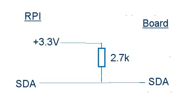
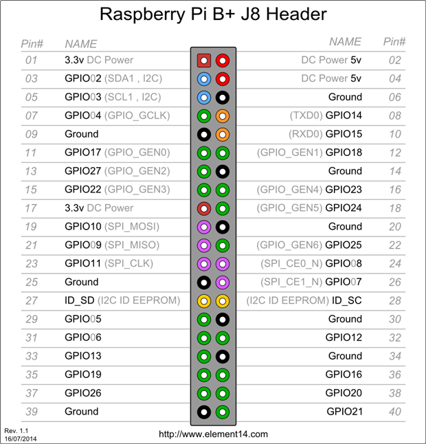
From what I can see, this appears to be I2C, however I have hooked this up to a Raspberry Pi I have and tried to run i2cdetect, and it is not detected as a device. It's also clearly not SPI as there is no RX line on the temperature sensor.


Any ideas, great minds of element14?


Josh

  • Sign in to reply
  • Cancel

Top Replies

  • sunnyiut
    sunnyiut over 10 years ago in reply to hawkeyethehacker +2
    ummm... i am not sure, but i think pi B has 1.8k pull ups for i2c lines. i don't know about pi B+. however, u can give it a try and let us know. 7420 suggests typically 10k for interfacing. Edit -> for…
  • shabaz
    shabaz over 10 years ago in reply to hawkeyethehacker +1
    The SDA and SCL pins are floating, and need to be connected to +3.3V using resistors, i.e. basically something like this (and repeat for the SCL line too). And connect the 0V line between the board and…
  • shabaz
    shabaz over 10 years ago in reply to hawkeyethehacker +1
    Hi Joshua, Did you really mean GPIO5, or did you mean pin5? The clock should be connected to pin5, i.e. GPIO03. Could you confirm this is what you've got? Similarly for Data, that should be pin3, i.e.…
Parents
  • shabaz
    0 shabaz over 10 years ago

    Hi Joshua,


    From what I can tell, the eval board doesn't have pull-ups, and I've no idea if the RPI has pull-ups, but I suspect it doesn't. In that case, you'll need a couple of resistors, i.e. something like 2.7k resistors from the SDA and SCL lines to +3.3V will be needed.

    Good luck with your project!

    • Cancel
    • Vote Up 0 Vote Down
    • Sign in to reply
    • Verify Answer
    • Cancel
  • hawkeyethehacker
    0 hawkeyethehacker over 10 years ago in reply to shabaz

    I have 1k ohm, not sure about 2k.

    • Cancel
    • Vote Up 0 Vote Down
    • Sign in to reply
    • Verify Answer
    • Cancel
  • shabaz
    0 shabaz over 10 years ago in reply to hawkeyethehacker

    The SDA and SCL pins are floating, and need to be connected to +3.3V using resistors, i.e. basically something like this (and repeat for the SCL line too). And connect the 0V line between the board and the RPI too.

    image

    1k is a bit low, something between 2k and 5k is good. If you don't have this, use (say) two 10k resistors in parallel to get you 5k, or two 1k resistors in series to give you 2k.

    • Cancel
    • Vote Up +1 Vote Down
    • Sign in to reply
    • Verify Answer
    • Cancel
  • hawkeyethehacker
    0 hawkeyethehacker over 10 years ago in reply to shabaz

    Great, thank you. I'll give this a try once I have some 2k-5k resistors and I'll let you know how it goes. Marking as helpful for now

    • Cancel
    • Vote Up 0 Vote Down
    • Sign in to reply
    • Verify Answer
    • Cancel
  • sunnyiut
    0 sunnyiut over 10 years ago in reply to hawkeyethehacker

    ummm... i am not sure, but i think pi B has 1.8k pull ups for i2c lines. i don't know about pi B+. however, u can give it a try and let us know.

    7420 suggests typically 10k for interfacing.


    Edit ->

    for B+

    I2C1_SDA and I2C1_SCL pins 3 and 5 of the GPIO header should be used and they are pulled up with 1.8k. I2C0 [GPIO's 28 and 29 (SDA0 and SCL0)] has pull up resistors but is occupied by camera interface. ID_SD and ID_SC is used for EEPROM which does not have pull up resistors. So if ID_SC and ID_SD are used then external pull ups are needed.

    • Cancel
    • Vote Up +2 Vote Down
    • Sign in to reply
    • Verify Answer
    • Cancel
  • shabaz
    0 shabaz over 10 years ago in reply to sunnyiut

    Ahh you're right. Sorry Joshua for leading you down the wrong path.

    I can see it described here: http://www.raspberrypi.org/forums/viewtopic.php?f=44&t=7664

    (there are no schematics for the RPI to confirm this for ourselves).


    Looks like the issue is something else : (


    If you can post a photo or description of what pins you've connected up, perhaps something can be spotted, but it seems you're doing the right thing if you've connected up the SDA and SCL pins on the RPI to the correct pins on the board, and connected up 0V together between the RPI and the board, and provided the supply (which could also be taken from the RPI).

    • Cancel
    • Vote Up 0 Vote Down
    • Sign in to reply
    • Verify Answer
    • Cancel
  • hawkeyethehacker
    0 hawkeyethehacker over 10 years ago in reply to shabaz

    I have the module connected as follows:


    RasPi GPIO Pin No.Breakout Board
    3V3VCC
    GPIO2Data
    GPIO3Clock
    GroundGround


    I don't have a photo yet but I'll try and get one taken tomorrow. Thanks for your help, everyone.


    EDIT: Adjusted Pin Name above in regards to the comment below

    • Cancel
    • Vote Up 0 Vote Down
    • Sign in to reply
    • Verify Answer
    • Cancel
Reply
  • hawkeyethehacker
    0 hawkeyethehacker over 10 years ago in reply to shabaz

    I have the module connected as follows:


    RasPi GPIO Pin No.Breakout Board
    3V3VCC
    GPIO2Data
    GPIO3Clock
    GroundGround


    I don't have a photo yet but I'll try and get one taken tomorrow. Thanks for your help, everyone.


    EDIT: Adjusted Pin Name above in regards to the comment below

    • Cancel
    • Vote Up 0 Vote Down
    • Sign in to reply
    • Verify Answer
    • Cancel
Children
  • shabaz
    0 shabaz over 10 years ago in reply to hawkeyethehacker

    Hi Joshua,


    Did you really mean GPIO5, or did you mean pin5?

    The clock should be connected to pin5, i.e. GPIO03. Could you confirm this is what you've got?

    Similarly for Data, that should be pin3, i.e. GPIO02.

    These are the blue pins in the image below.


    image

    • Cancel
    • Vote Up +1 Vote Down
    • Sign in to reply
    • Verify Answer
    • Cancel
  • hawkeyethehacker
    0 hawkeyethehacker over 10 years ago in reply to shabaz

    Apologies, yes. I was following a different diagram. image

    • Cancel
    • Vote Up 0 Vote Down
    • Sign in to reply
    • Verify Answer
    • Cancel
element14 Community

element14 is the first online community specifically for engineers. Connect with your peers and get expert answers to your questions.

  • Members
  • Learn
  • Technologies
  • Challenges & Projects
  • Products
  • Store
  • About Us
  • Feedback & Support
  • FAQs
  • Terms of Use
  • Privacy Policy
  • Legal and Copyright Notices
  • Sitemap
  • Cookies

An Avnet Company © 2025 Premier Farnell Limited. All Rights Reserved.

Premier Farnell Ltd, registered in England and Wales (no 00876412), registered office: Farnell House, Forge Lane, Leeds LS12 2NE.

ICP 备案号 10220084.

Follow element14

  • X
  • Facebook
  • linkedin
  • YouTube