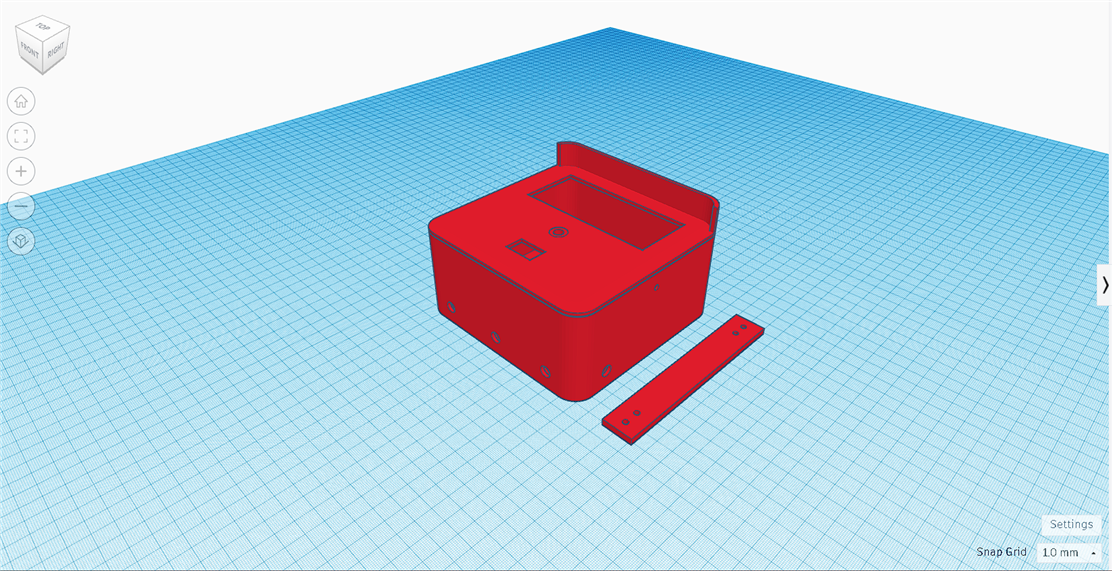
Hello Guys, I will share my experience in the hardware and case assembly process for the Climate Change Monitoring System. To create a 3D design of the casing, I used Tinkercad software

Before printing, I used the Ultimaker Cura slicer software to change the 3D STL format to G-Code.

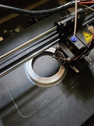
Next is the printing process using a 3D printer. With filament PLA+ 
After everything is finished, proceed to the assembly stage between the case and the electronic system that was created in the previous post.
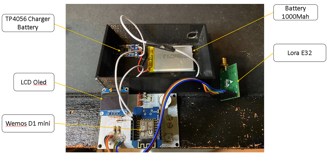
1.Assembly of the second node as a receiver

At the first node, the power source comes from a 1000Mah capacity battery, equipped with a 1A lithium charger, namely TP4056.
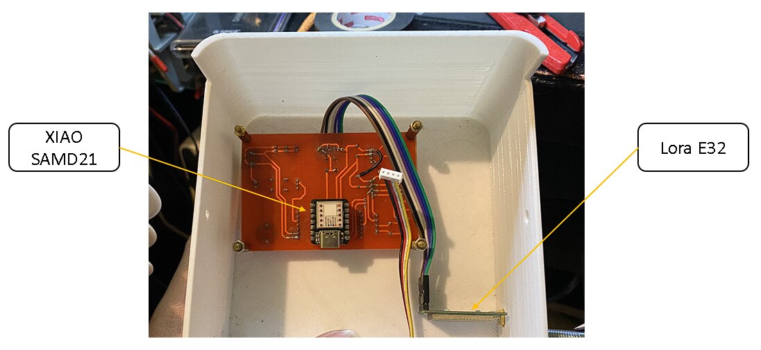
2. Next is the stage of assembling the first node

In the picture above, I placed the XIAO SAMD21 on the back of the PCB and Lora E32 On the Bottom of the PCB. here are the assembly results of the first node:

The first node uses resources from a 10Wp 12V Solar Panel, reduced using a Mini MPPT to 5V with a maximum electric current of 5A, then the power from the MPPT will be stored in a battery with a capacity of 6000Mah.
(DHT 20 Sensor)
(Hall Effect Sensor to read rainfall)
(Overall Results after assembly)
There are two elements of green technology in this innovation, as follows:
- The electrical resources used come from renewable energy, namely Solar Panels with a capacity of 12V/10Wp.
- The casing used is made from environmentally friendly PLA+.
That's the process of assembling the Climate Change Monitoring System, thank you for reading my blog, next I will post testing of this innovation on coffee plantations.

