I welcome you to my 4th blog post as part of Summer of Sensors Design Challenge in category In the Air Tonight. In 1st blog post I described my plans as part of this contest, then in 2nd part I shown hardware of the Renesas ZMOD4510 Evaluation Kit and in previous 3rd blog post I shown evaluation software provided by Renesas. I did not write any code yet and this will change today. In this 4th blog post I will show my first thought about using ZMOD4510 Outdoor Air Quality sensor with microcontroller. For controlling sensor, I will use Renesas RA2L1 low-power microcontroller which I will use later in project. For developing I will use Renesas e2 studio eclipse-based IDE and I will use Renesas FSP (Flexible Software Package). Renesas refers this ecosystem as Renesas Quick-Connect IoT and both RA2L1 and ZMOD4510 sensors are included so sensor can be easily integrated to the project.
Creating project
The first step after opening e2 studio is create new project.
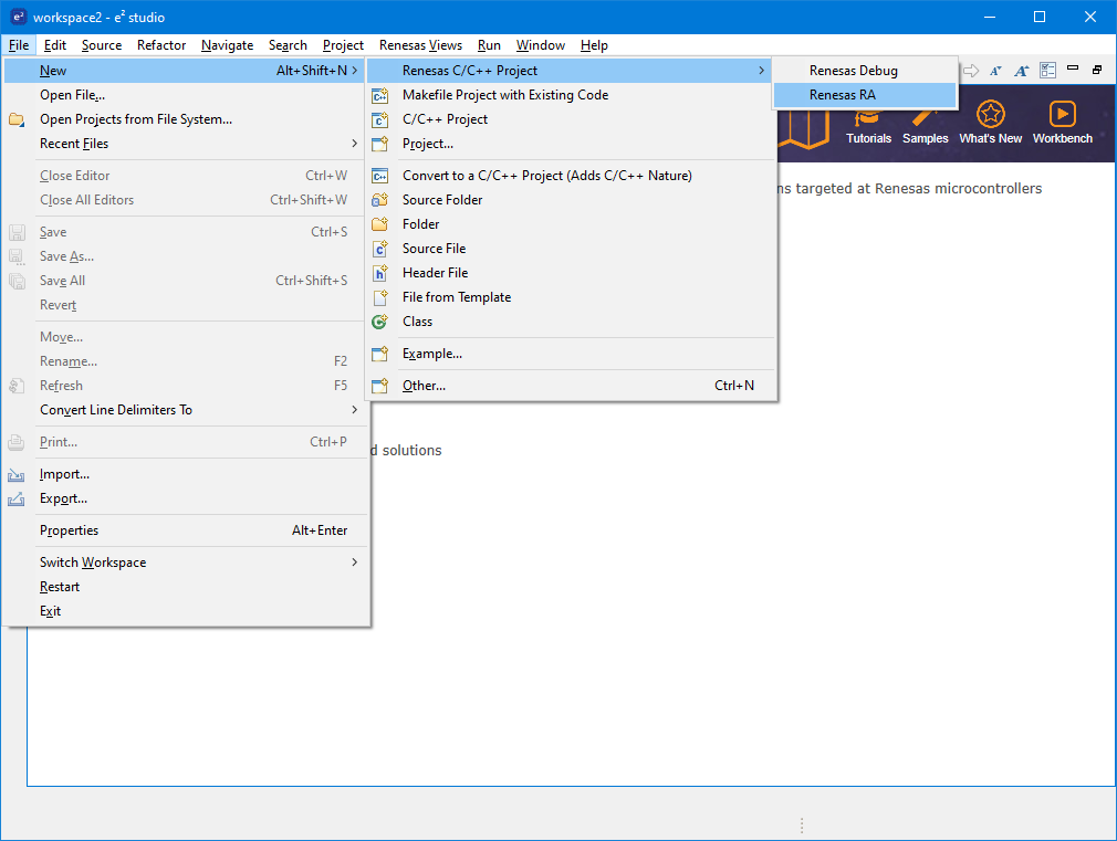
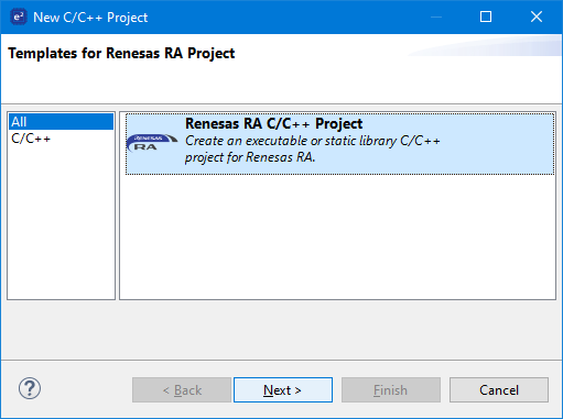
In the dialog window select Renesas RA C/C++ Project and click Next.
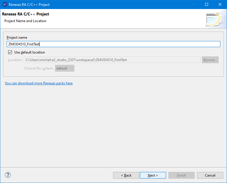
Enter some name and click Next.
At next page select used kit in Board dropdown. In my case it EK-RA2L1. Then click Next.
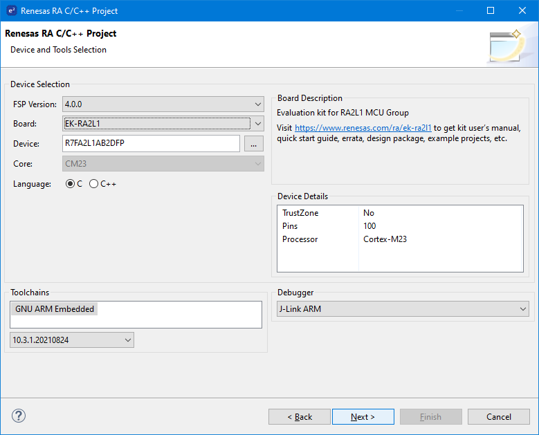
At next page just click Next.
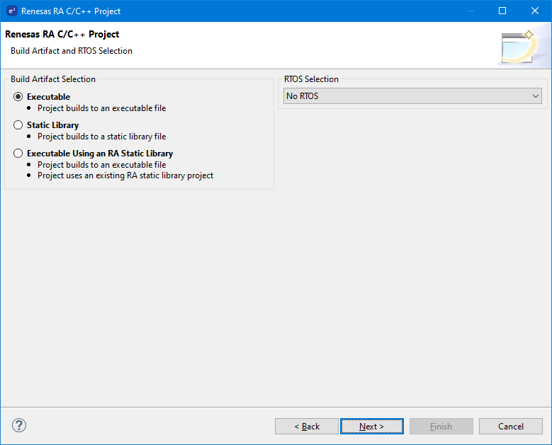
At final page select Minimal template. I recommend unkarking Use Renesas Code Formatter. Then click Finish.
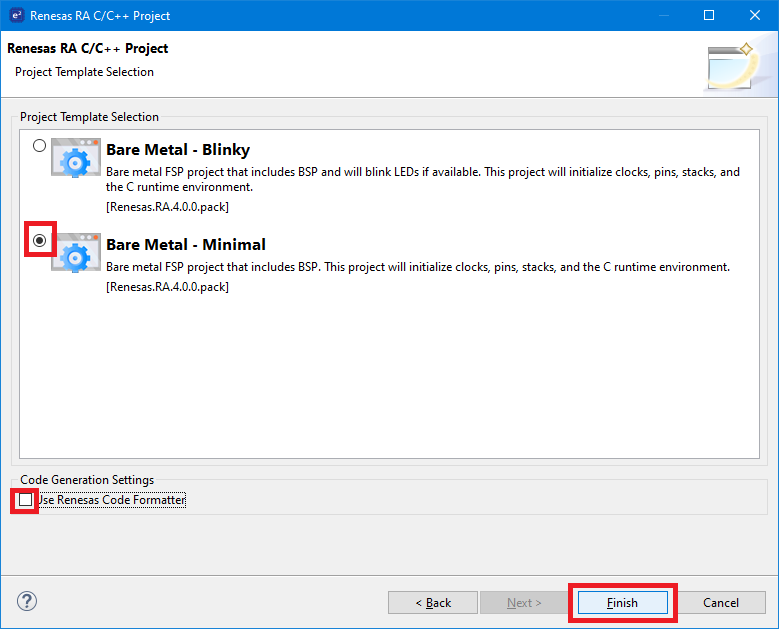
After creating project e2 studio opens configuration.xml file and GUI editor of this file for you.
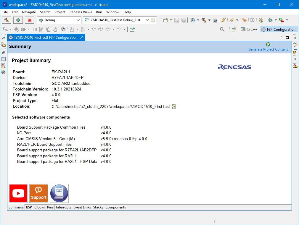
Now we will include driver for ZMOD4510 sensor. As I have said at the beginning because ZMOD4510 is included in Renesas Quick-Connect IoT project, then including driver is very easy. Go to Stacks tab. Click New Stack > Sensor > ZMOD4xxx Gas Sensor (rm_zmod4xxx).
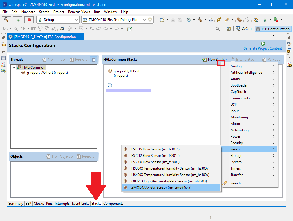
Stack label is red indicating some error. In this case we need to configure lower layers of stack. First click Add Requires ZMOD Library. Then select New and select algorithm used for computing air quality computation. For ZMOD4510 Outdoor Air Quality sensor there are two algorithms. I selected 2nd low-power generation.
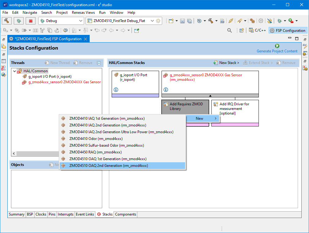
After adding this new layer first stack level will change from Red to Black indicating that we fixed the stack, but similar issue started occurring on new layer.
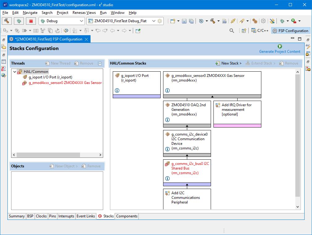
The next step for fixing is adding I2C communication peripheral. RA2L1 MCU has two possible peripherals. Serial Communication Interface (SCI) which can communicate using basic I2C and dedicated IIC peripheral supporting advanced features of I2C protocol. You can select whatever you want. Both will work. I selected advanced IIC:
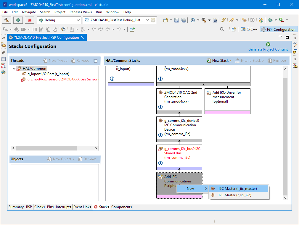
New stack layers appears but for operation we do not need any additional layers. If you want to use interrupt you can add layer for this.
Now we have added stacks for and libraires for our sensor, but you may notice that we did not specify I2C pins (and IRQ pin if you decided to use them) anywhere. For showing default pinout you need open Properties window (you most probably see this window, but I hide it for saving space at screenshots). Click the I2C driver stack and at the end of Properties list you should see that I2C driver with pins P407 and P408 was used:
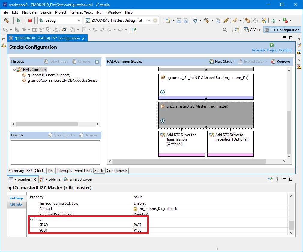
P407 and P408 are exposed on Arduino connector on EK-RA2L1 board. If you for some reason need to change them, then go to Pins tab, select IIC0 peripheral and change pins mapped for this peripheral. After adjusting you can go back and check that pin change promoted to g_i2c_master0 stack.
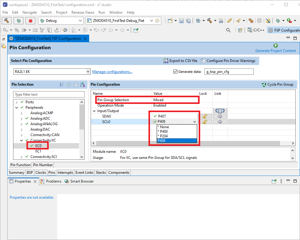
Note that if you do not find any suitable pin you can change IIC0 to IIC1 peripheral. This can be changed in stack settings under Channel property (change 0 to 1).
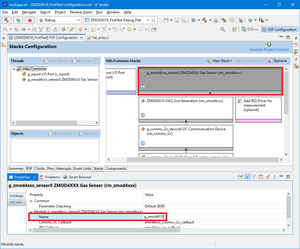
The last configuration is renaming the first stack. Currently it is named g_zmod4xxx_sensor0, but because I exactly know what sensor I use, I will rename it to g_zmod4510 and this I will reference in source code. Click the top stack and in preparties window change its name:
For now, stacks are configured. Let’s go connect sensor to board.
Connection
For connecting sensor to board, you need to connect 5 wires (or 6 + pull-up resistor if you decided to use interrupt). Two of them are power pins and remaining two are I2C signals. Schematically connection looks as follows:
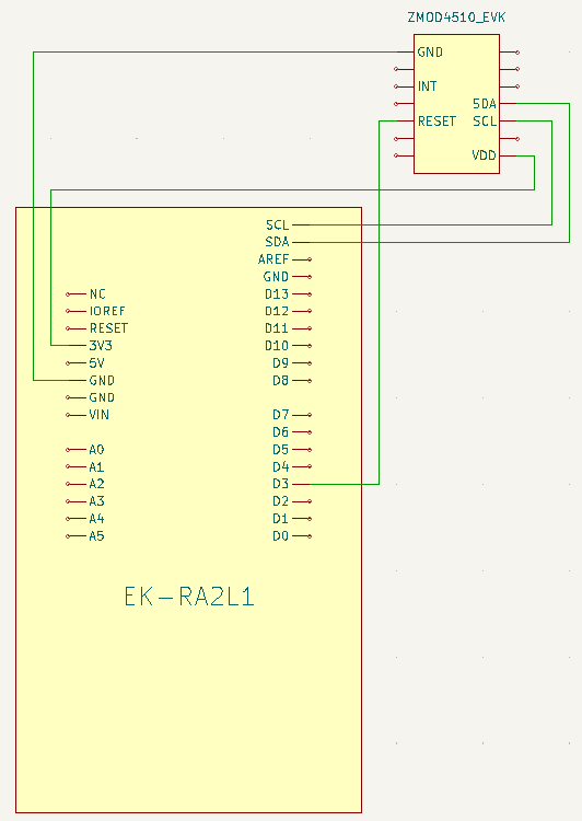
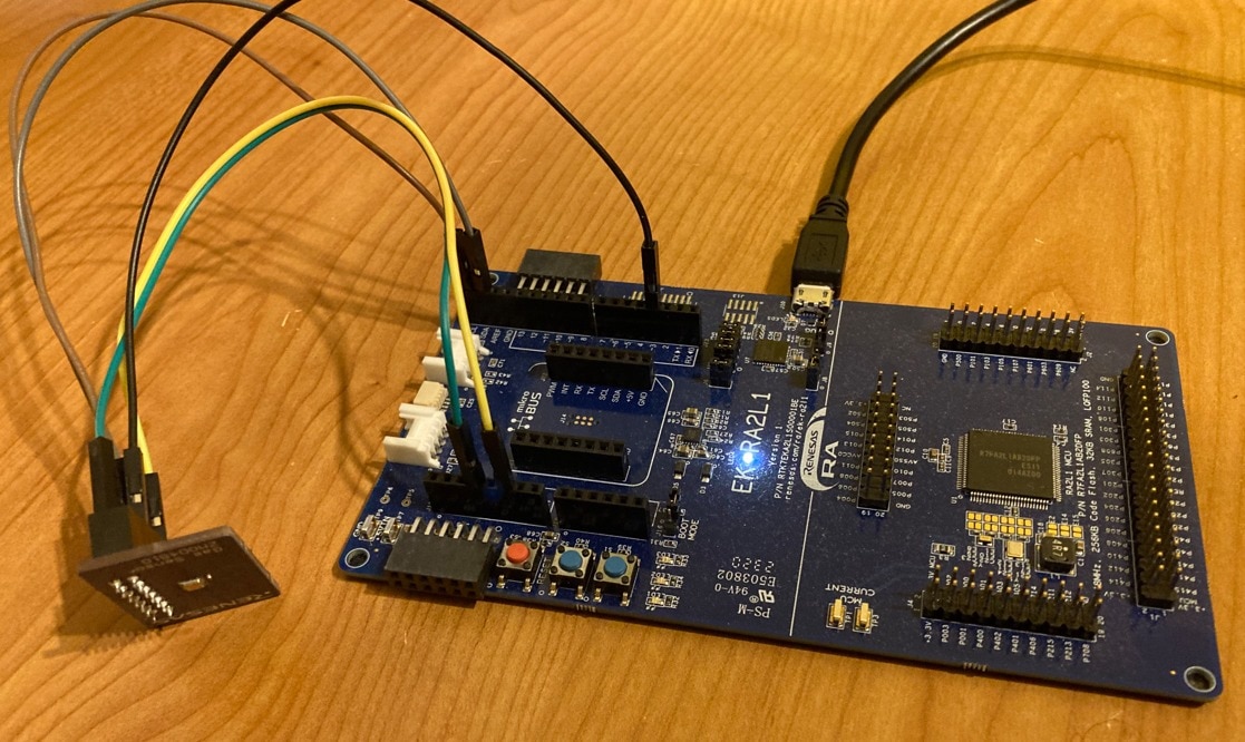
Before connecting check orientation of ZMOD4510 connector. Board has no silkscreen. Connection above matches pinout when watching board from top, not the bottom connector side (but please double check it. I was confused by this)! Rotating sensor will permanently damage them because when rotated you reverse power pins polarity. I recommend placing sensor back to communication board and using voltmeter to check at which pin is positive voltage and where the ground is. Double check this before powering.
In real world connection can look as follows:
Project settings
Before we start coding, we need to adjust some project settings. Right click the project in Project Explorer and click Properties.
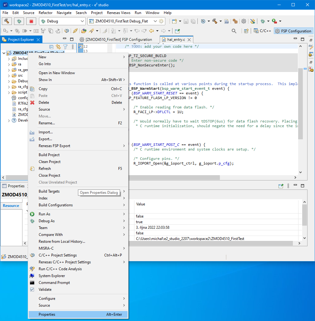
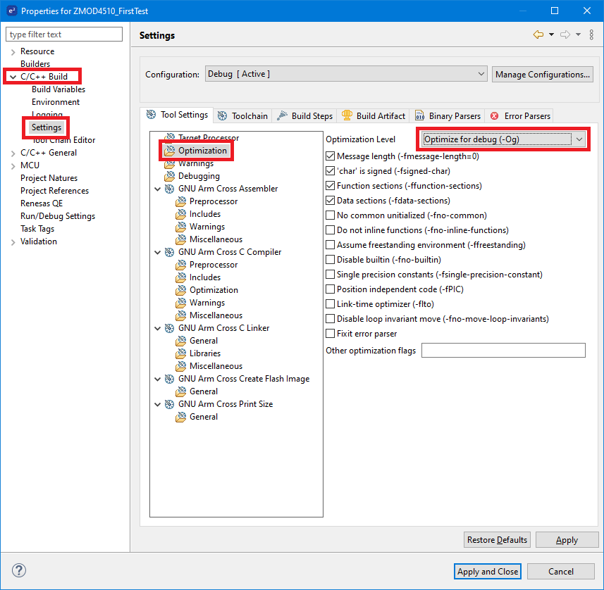
Then go to C/C++ Build > Settings section. At Tool Settings tab select Optimization and change O2 to Og:
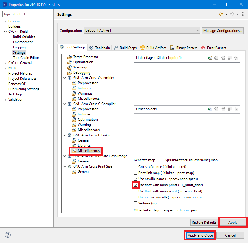
Then go to GNU Arm Cross C Linker > Miscellaneous section and mark Use float with nano printf. Then confirm settings dialog window. Eclipse will ask you about rebuild. You can choose whatever you want because we have no code yet, so it does not make sense for us.
SEGGER RTT Library
If you want to write debug outputs then you need to use external UART or SEGGER RTT Library. How to integrate SEGGER RTT Library to the e2 studio project I described in my Using I2C, SPI and DMA on Renesas RA2L1 (part 1) tutorial.
Code
Now we can start writing code which will use stacks which we added earlier to the project.
In Project Explorer open hal_entry.c file and go to first line of hal_entry function. In this function we will today write whole program.
Most of the time we will use functions for controlling ZMOD4510 sensor and its stack. All these functions are prefixed with RM_ZMOD4XXX. You can list them by pressing Ctrl + Space in editor:
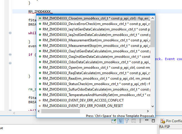
Functions are designed very similar to any other functions on Renesas RA platform. They accept as first parameter control handle and initialization function requires configuration handle. Both structures are generated by code generator and are named with prefix g_zmod4510 which we have used in stack configuration.
Resetting sensor
The first step after powerup is resetting sensor. This is done by toggling GPIO. On Renesas MCU this can be done using following code snippet. It set reset pin for 10ms low and then it set it back to high and wait 10ms for sensor boot.
R_IOPORT_PinWrite(&g_ioport_ctrl, ARDUINO_D3_MIKROBUS_PWM, 1);
R_BSP_SoftwareDelay(10, BSP_DELAY_UNITS_MILLISECONDS);
R_IOPORT_PinWrite(&g_ioport_ctrl, ARDUINO_D3_MIKROBUS_PWM, 0);
R_BSP_SoftwareDelay(10, BSP_DELAY_UNITS_MILLISECONDS);
R_IOPORT_PinWrite(&g_ioport_ctrl, ARDUINO_D3_MIKROBUS_PWM, 1);
R_BSP_SoftwareDelay(10, BSP_DELAY_UNITS_MILLISECONDS);
Opening I2C Driver
Before we can use sensor, we need to initialize I2C driver. This is done using following line of code.
R_IIC_MASTER_Open(&g_i2c_master0_ctrl, &g_i2c_master0_cfg);
Opening ZMOD4510 Driver
After initializing I2C bus we can initialize ZMOD4510 library. This is done using following line of code:
RM_ZMOD4XXX_Open(&g_zmod4510_ctrl, &g_zmod4510_cfg);
ZMMOD4510 Driver Callback
Every operation which results to I2C bus transaction is in ZMOD4510 stack implemented asynchronously. We start the action and library then immediately return control to us, but operation completes later. For this reason, we need to implement callback function in which we can notice that previously executed operation completed. Callback functions must be named zmod4xxx_comms_i2c_callback. This named is entered in stack configuration as default. Callback will get one argument which is pointer to rm_zmod4xxx_callback_args_t structure. We will implement callback trivially. We will use global variables which we will write in callback (which is called from I2C controller interrupt) and process these global variables in main loop. We will need 2 global variables:
static int eventOccured = 0;
static rm_zmod4xxx_event_t lastEvent = -1;
Now we can write callback function and save received status to these global variables.
void zmod4xxx_comms_i2c_callback(rm_zmod4xxx_callback_args_t* p_args) {
      lastEvent = p_args->event;
      eventOccured = 1;
}
Main loop
Code described in following sections will be placed in infinite loop. Go back to hal_entry function and add following infinite loop. All next code will be placed in this loop.
while (1) {

}
Starting Measurement
The first step when using ZMOD4510 is starting measurement.
RM_ZMOD4XXX_MeasurementStart(&g_zmod4510_ctrl);
Starting measurement is one of the operations which triggers I2c operation so after calling it, we need to wait until I2C operation completes and library calls our callback. This is indicated by eventOccured global variable declared in previous section. I use __WFI instruction for reducing CPU power consumption when waiting.
while (eventOccured == 0) {
      __WFI();
}
eventOccured = 0;
After operation complete, we can check for error. In case of success, we need to wait 2 seconds and then check status.
if (lastEvent == RM_ZMOD4XXX_EVENT_SUCCESS) {
      // OAQ v2 require 2s delay
      R_BSP_SoftwareDelay(2000, BSP_DELAY_UNITS_MILLISECONDS);
} else {
      SEGGER_RTT_printf(0, "Error after RM_ZMOD4XXX_MeasurementStart. Event code: %d.\r\n", lastEvent);
      while (1) {
            __WFI();
      }
}
Checking for conversion status
Next step is checking conversion status. This is asynchronous operation, so we need to start it and wait for it. After waiting for it we will check status and possibly report error:
RM_ZMOD4XXX_StatusCheck(&g_zmod4510_ctrl);

while (eventOccured == 0) {
      __WFI();
}
eventOccured = 0;

if (lastEvent != RM_ZMOD4XXX_EVENT_MEASUREMENT_COMPLETE) {
      SEGGER_RTT_printf(0, "Error after RM_ZMOD4XXX_StatusCheck. Event code: %d.\r\n", lastEvent);
      while (1) {
            __WFI();
      }
}
We need to call additional error checking because we use second generation of OAQ (Outdoor Air Quality) algorithm.
Reading data
Now after waiting for data and checking their availability and validity we can read them. Similarly, to most previous operation it is asynchronous operation and we must wait until callback get called.
rm_zmod4xxx_raw_data_t rawData;

RM_ZMOD4XXX_Read(&g_zmod4510_ctrl, &rawData);

while (eventOccured == 0) {
      __WFI();
}

eventOccured = 0;

if (lastEvent != RM_ZMOD4XXX_EVENT_SUCCESS) {
      SEGGER_RTT_printf(0, "Error after RM_ZMOD4XXX_Read. Event code: %d.\r\n", lastEvent);
      while (1) {
            __WFI();
      }
}
Now we have collected raw data but these data are quite a useless. Instead, we need to feed them to the AI algorithm implemented by Renesas. Before we can do this, we should adjust temperature and humidity setting which is used for compensations. But even before we can set this values, we need to check for device errors again:
RM_ZMOD4XXX_DeviceErrorCheck(&g_zmod4510_ctrl);

while (eventOccured == 0) {
      __WFI();
}
eventOccured = 0;

if (lastEvent != RM_ZMOD4XXX_EVENT_SUCCESS) {
      SEGGER_RTT_printf(0, "Error after RM_ZMOD4XXX_DeviceErrorCheck. Event code: %d.\r\n", lastEvent);
      while (1) {
            __WFI();
      }
}
And now we can set temperature and humidity for compensations.
Setting Temperature and Humidity
Because I do not have HS4000-EVK and currently I do not connect any other temperature and humidity sensor I hardcoded values from independent meters. Temperature and humidity settings affects only local algorithm and do not need to communicate with sensor, then we do not need to wait for callback (no callback occur after this operation).
RM_ZMOD4XXX_TemperatureAndHumiditySet(&g_zmod4510_ctrl, 14, 60);
Calculating Air Quality indexes
Last step before printing results is feeding rawData to algorithm and getting results. It is local operation which runs on microcontroller CPU and do not communicate with sensor. For this reason, we do not need to wait for callback.
rm_zmod4xxx_oaq_2nd_data_t data;
fsp_err_t fStatus = RM_ZMOD4XXX_Oaq2ndGenDataCalculate(&g_zmod4510_ctrl, &rawData, &data);
In this case I saved return value of function call. In fact, I did this in all previous cases but for simplicity I removed these error checking from code snippets in this blog (in project attached at the end of this blog posts these checks are present). But in this case error check is important. We must tolerate one error. After powerup It took one hour until measurements stabilise. For this reason, first hour library returns error code FSP_ERR_SENSOR_IN_STABILIZATION. I added check and I early end main loop iteration by continue command in case of this situation.
if (fStatus == FSP_ERR_SENSOR_IN_STABILIZATION) {
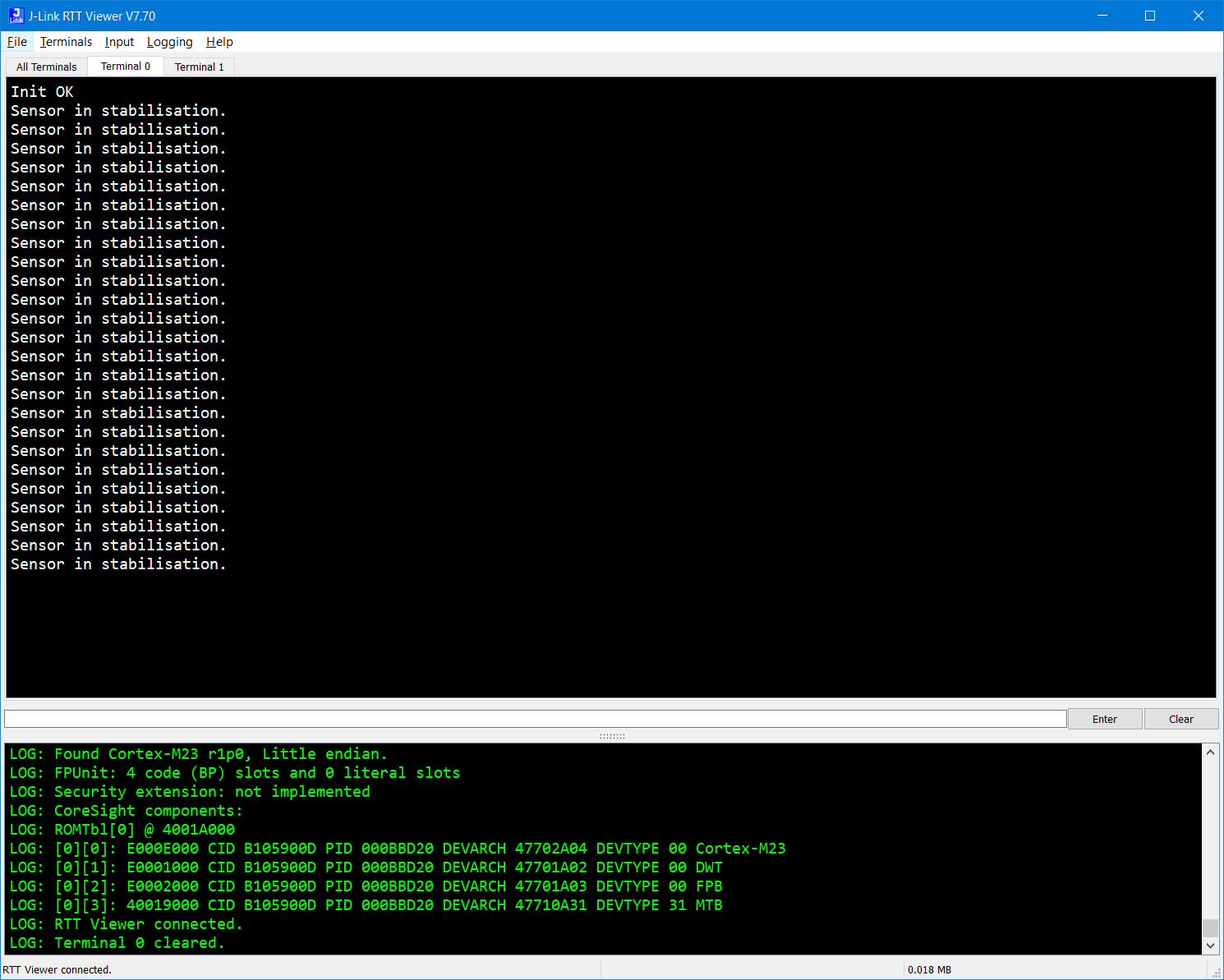
      SEGGER_RTT_printf(0, "Sensor in stabilisation.\r\n");
      continue;
}
Printing results
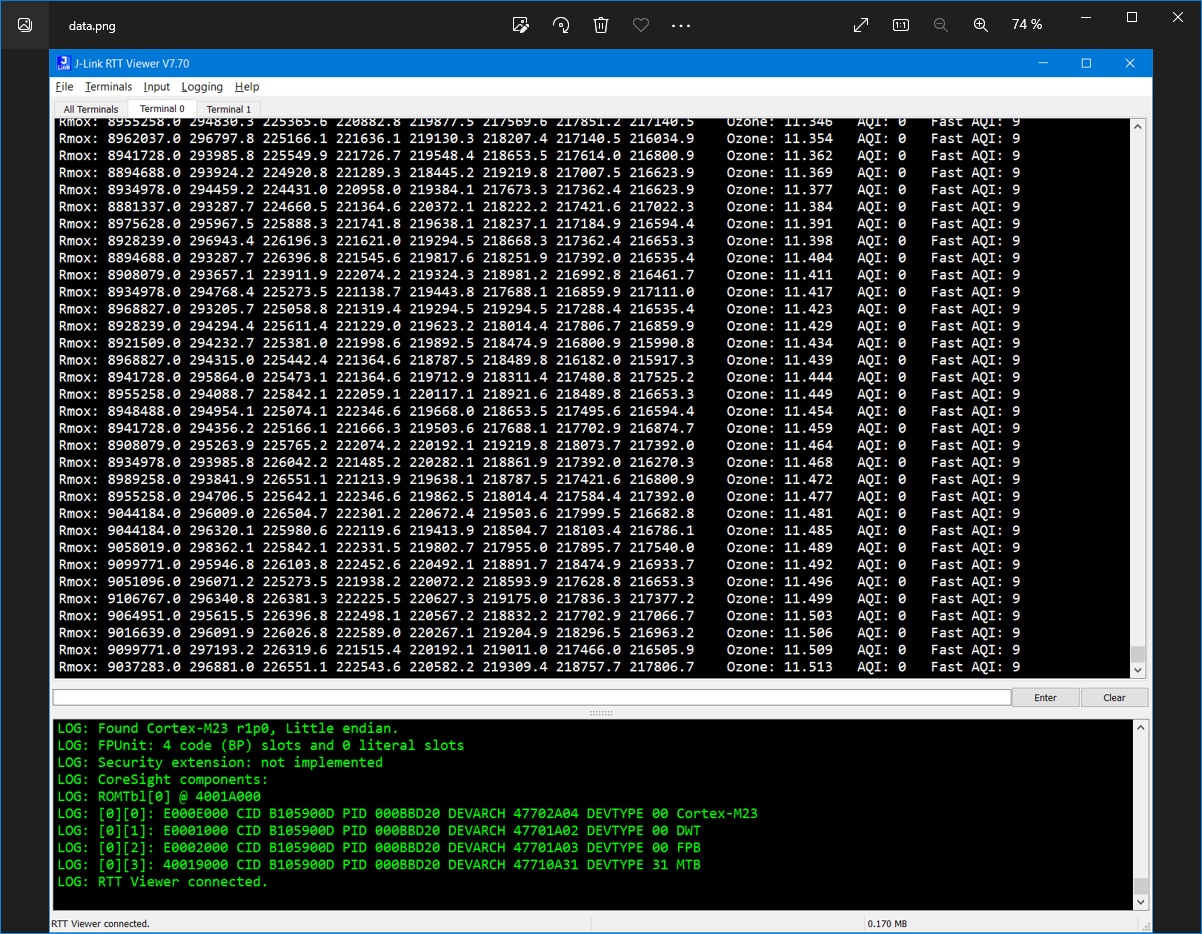
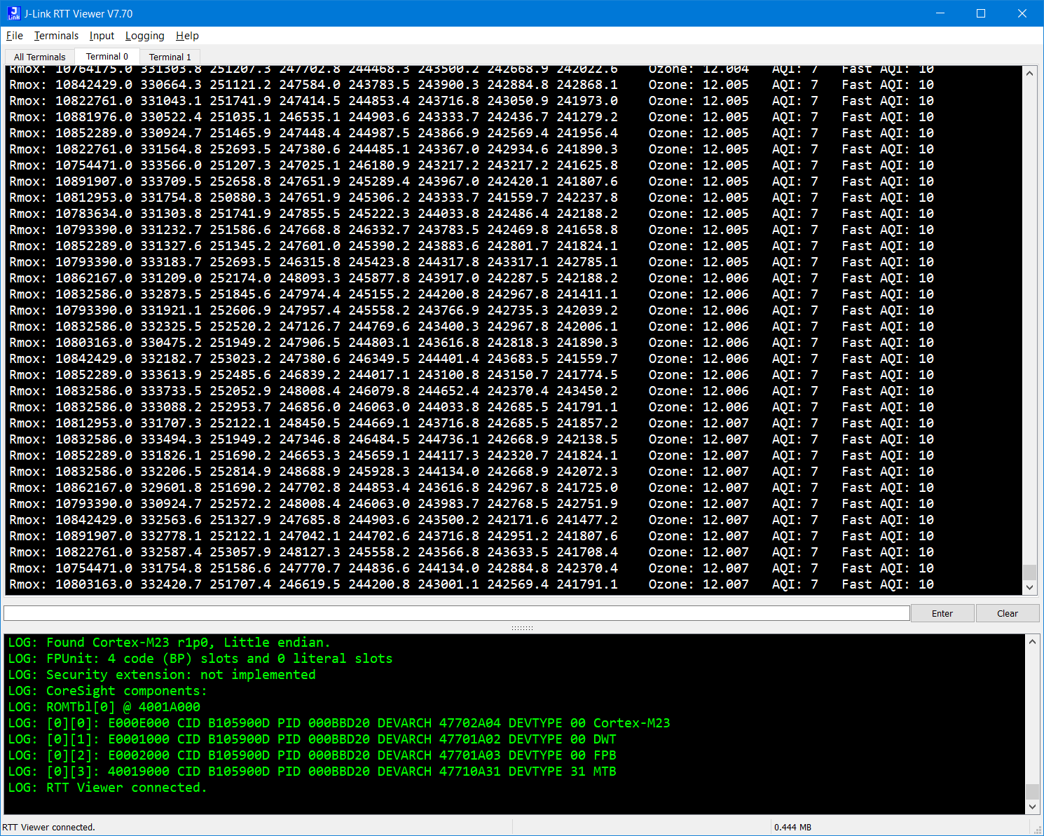
After this we can (add checking for other errors and) print results. Resistance of MOX chemically sensitive element as part of sensor is presented as an array of values (note that raw data were also presented as an array). I print all values. Because many values are float, I need to print them to the buffer first because SEGGER RTT library do not support printing floats.
SEGGER_RTT_printf(0, "Rmox: ");
for (int i = 0; i < 8; i++) {
      snprintf(buffer, sizeof(buffer), "%.1f ", data.rmox[i]);
      SEGGER_RTT_printf(0, buffer);
}

snprintf(buffer, sizeof(buffer), "   Ozone: %.3f   AQI: %d   Fast AQI: %d\r\n", data.ozone_concentration, (int)data.epa_aqi, (int)data.fast_aqi);
SEGGER_RTT_printf(0, buffer);
Testing
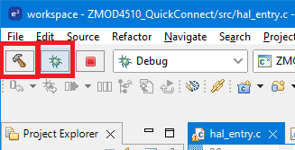
Now click the build and debug icons in top menu.
After deploying to the device, you need to resume all breakpoint hit by continue button. After doing this you can start SEGGER RTT viewer and check outputs. At beginning you should see Sensor in stabilisation messages:
After one hour some data start occurring:
Later AQI also increases from zero:
Summary
This is all from this tutorial. In this tutorial I shown first reading and processing of data from microcontroller. Because contest is sponsored by Renesas I used their microcontroller which is good choice because integration of ZMOD4510 sensor library is ultra-easy on this platform. Currently I work on integration Wi-Fi connectivity and cloud application. Next two blogs most probably will be about this. Later I want to build some DIY box for my device and place it outside. At last, I want to write some analysis of measured data after some longer period of time.
Thank you for your time. Thanks for reading this blog post and stay tuned on my further progress.
Next blog: Blog #5: Adding Connectivity to the Project using Renesas DA16600 Wi-Fi Module

