Hello everyone. I welcome you to my 6th blog as part of Summer of Sensors Design Challenge and category In the Air Tonight category. In my previous blog posts, I described Renesas ZMOD4510 Outdoor Air Quality sensor, I shown its evaluation kit software and later I started creating my project for experimenting with sensor from microcontroller and sending measured data to the cloud. For summary, here is list my previously posted blog posts as part of this competition:
- Blog #1: Introduction to my Air Quality Experiments
- Blog #2: Unboxing Renesas ZMOD4510-EVK
- Blog #3: Experimenting with ZMOD4510-EVK Software
- Blog #4: Tutorial: Using ZMOD4510 with Renesas EK-RA2L1 and FSP
- Blog #5: Adding Connectivity to the Project using Renesas DA16600 Wi-Fi Module
DIY Box
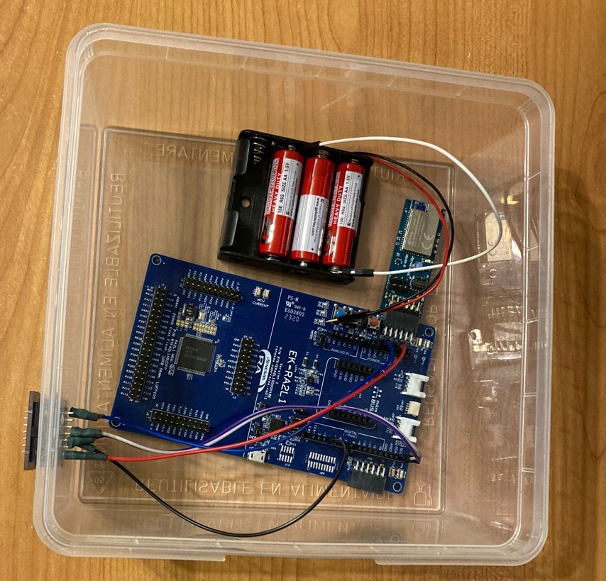
Because ZMOD4510 is Outdoor Air Quality Sensor It is crucial to test it outside. For at least basic water and dust resistance of other electronics I built box. I used plastic box which I had. I do not remember what this box was originally used for but in previous years I used it as a general-purpose storage box. It has detachable cover. It is plastic and transparent.

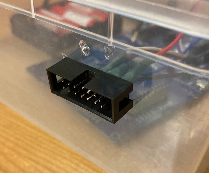
At the end was box was covered by plastic cover. But sensor need to be placed outside, for this reason I made holes for IDC connector and connected ZMOD4510 sensor board outside of the board. Other electronics including batteries are inside.

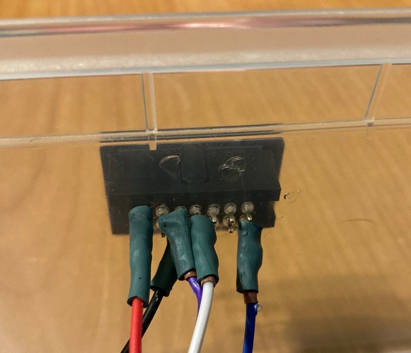
From back side I soldered wires and isolated them using shrink tube.

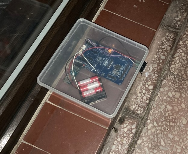
I decided to do this for allowing full access of fresh outside air to the sensor. Disadvantage is that sensor is sensitive to water (rain). I decided to place box under the roof, so I do not consider this as a big issue. At least for my first experiments. Later I will maybe find some better case for it.
Battery Power
As you can see briefly at previous pictures, I used 3xAA batteries for powering the circuit. Each cell has 1.6V at the beginning, so I have 4.8 volts. Adding one more battery violates onboard LDO Absolute Maximum ratings. I connected this to the 5V branch of the EK-RA2L1 board. 5V branch is connected to onboard LDO which creates 3.3 V for powering RA2L1 MCU, onboard debugger MCU, and Wi-Fi Module.
Power Consumption Optimization
For a optimizing power consumption I decided to desolder bright white LED which lit all the time (it is directly connected to 3.3V power supply. For some reason, I was unable to desolder it with hot air and instead I destroyed it by pressure of tweezers. But it is not big issue for me. Now it does not consume anything.
I did not desolder debugger LED and I also did not cut solder bridge for disconnecting debugger MCU. It is basically because I want to use debugger on this board in the future. I am not sure about power consumption of debugger MCU but I think it should not be very high. Similarly, debugger LED do not lit all the time. Instead, it flashes.
Going Outside
After I assembled to box content, I closed it and placed it outside on balcony. I connected battery and waited half hour for first data. After powerup device do not send any data to the cloud because it is in stabilization phase. After half hour it begin sending data to the cloud, so I went sleep.

Summary
Thank you for reading this blog. This is all from my first experiments with ZMOD4510 Outdoor Air Quality Sensor as far. It was quite short but next blog will summarize my results. In the meantime, my device ruined its battery. My estimations about power consumption were quite inaccurate and device drained battery very fast. Next, I will describe techniques which I used for lowering power consumption, so next time I hope it will run longer on the battery and gets more data. Contest ending in three days. Now I have completed all what I want to complete. Currently I am only intensively working on texts of my last blogs. They are coming soon.
Thank you for reading this blog post and stay tuned for my last blogs. If you have any question, feel free to ask in comments in below.
Next blog: Blog #7: Reducing Power Consumption

