


 BLOG# 5 - BPM Uno – Redesign and Implementation. This is my final blog for the Summer of Sensors -- Under Pressure Design Challenge.. I wanted to make the judges of the challenge, aware that this blog puts the finishing touches on my design. It demonstrates my Patient Beats Per Minute Heart Rate Monitor in operation. I have posted a 6th blog including my experiments and research on the MikroE LSM6DSL Click. This blog is more of a proof of concept to get to understand the LSM6DSL capabilities. Due to time, I was unable to fit the LSM6DSL into my design, but decided to included my findings in this challenge blog series.
I found in the testing phase (blog#4), that the SSD1306 did not work along with the MikroE Heart Sensor. I decided to abandon the use of it and came up with another solution to display the BPM monitor information. This blog, will describe my redesign of my solution, using the Grove-LCD Display and some other Grove modules from my Grove Starter kit. I will then, present my implementation of the BPM Monitor.
I did learn quite a bit about the MIKROE clicks and I have only scratched the surface of what can be done with these clicks. I will also share my conclusions of using the kit and my idea for other experiments that I would like to try out. with the kit.
Redesign
Functional changes and improvements
- Replacing the SDD1306 with the Grove-LCD to display BPM Monitor Information.
- in addition to BPM values, Display SP02% values on the display
- Attach a buzzer from my Grove Starter kit to the Grove Base Shield. Program the buzzer to Buzz on every heartbeat detected.
- Attach an LED from the Grove Starter kit , and blink it on every heartbeat.
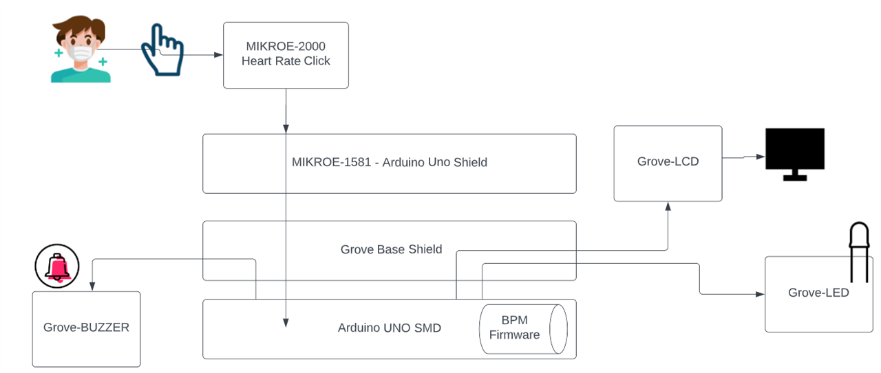
Block diagram
The following block diagram, shows the connections of this stacked prototype.
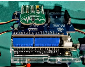
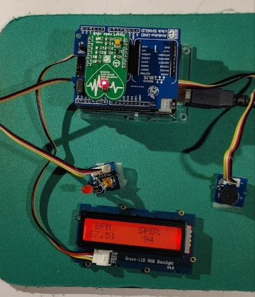
Here is a photo of the build connections shield stack.
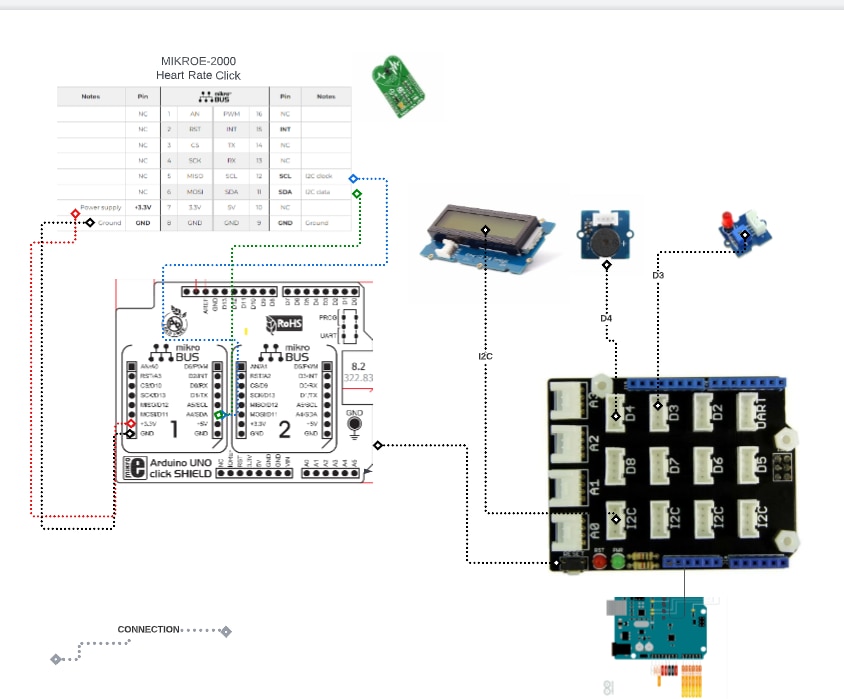
Electrical BUILD
- The following diagram, Shows the components used to build my Hardware prototype that the BPM firmware will run on.
- Uno SMD MCU
- Grove Uno Base Shield (stacked)
- Grove Starter kit modules attached the the Grove Shield.
- Grove-LCD
- Grove-Buzzer
- Grove-LED
- MIKROE Uno Shield, (stacked)
- MIKROE-2000 Heart Rate Click (stacked onto mikroBUS 1)
- The Grove Uno Base shield, with there pins matched up to the Header pins on the UNO.
- The 3 Grove Stater kit modules will attached to the appropriate Grove connectors of the shield.
- The MikroE Arduino Uno Click , will stack onto the Grove Base Shield.
- The MIKROE-2000 Heart Rate Click is paced onto mikroBUS 1, of the MIKROE Uno Shield. The connections used are depicted with a DOTTED line.
- The Build involves stacking the components onto each other and assuring the pins are lined up on there headers.
Implemented Application
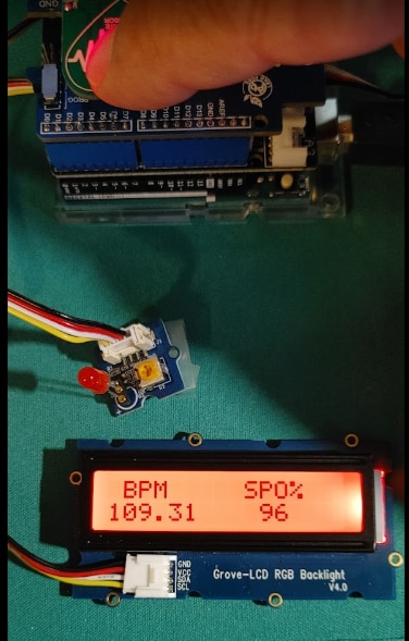
This section will show my implemented redesign and all the grove modules attached to it.
FIRMWARE CODE
FIRMWARE NAME: BPM_UNO_GROVE_MIKROE.ino
CODE:
/// BPM_UNO_GROVE_MIKROE
// This arduino sketch, captures a patents heart rate SPO% and there Beats Per Minute.
// on every heartbeat, a buzzer will sound and a RED led wil blink
// This script contains the logic from
// the grove OLED, buzzer,LED Examples
// the MAX30100_Minimal.ino library example, which uses the MAX30100 library
// Include Wire Library for I2C
#include <Wire.h>
#include "MAX30100.h"
#include "MAX30100_PulseOximeter.h"
// Grove OLED stuff
#include "rgb_lcd.h"
rgb_lcd lcd;
const int colorR = 150;
const int colorG = 0;
const int colorB = 0;
// sketch globals
//int count; //BPM Value
float count; //BPM Value
uint8_t count2 = 0; //SPO2% value
// MAX10100 CODE
#define REPORTING_PERIOD_MS 1000
// PulseOximeter is the higher level interface to the sensor
// it offers:
// * beat detection reporting
// * heart rate calculation
// * SpO2 (oxidation level) calculation
PulseOximeter pox;
uint32_t tsLastReport = 0;
const int pinLed= 3; // pin of led
int pinBuzzer= 4; // pin of buzzer
void Beep(int tone, int duration) {
// beep a tone for duration
//tone = tone + 1912;
tone = 3830 - tone;
duration = duration *10;
for (long i = 0; i < duration * 1000L; i += tone * 2) {
digitalWrite(pinBuzzer, HIGH);
delayMicroseconds(tone);
digitalWrite(pinBuzzer, LOW);
delayMicroseconds(tone);
}
}
void LED_Blink()
{
// analogWrite(pinLed, 256);
// delay(100);
// analogWrite(pinLed, 0);
//Blink the LED
for(int i=0; i<256; i++)
{
analogWrite(pinLed, i);
//delay(3); // change delay time can breath faster or slower
}
Beep(count,1);
//delay(100);
for(int i=254; i>=0; i--)
{
analogWrite(pinLed, i);
//delay(2); // change delay time can breath faster or slower
}
}
// Callback (registered below) fired when a pulse is detected
void onBeatDetected()
{
Serial.println("Beat!");
LED_Blink();
}
void displayValues(float v,uint8_t v2){
// set the cursor to column 0, line 1
// (note: line 1 is the second row, since counting begins with 0):
lcd.setCursor(0, 1);
lcd.print(" ");
lcd.setCursor(0, 1);
lcd.print(v);
lcd.setCursor(10,1);
lcd.print(v2);
// Serial.print(" Display: ");
// Serial.print(v);
}
void setup() {
Serial.begin(115200);
Wire.begin();
// set up the LCD's number of columns and rows:
lcd.begin(16, 2);
lcd.setRGB(colorR, colorG, colorB);
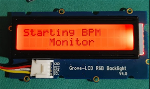
//Show start screen
lcd.setCursor(0,0);
lcd.print("Starting BPM ");
delay(100);
lcd.setCursor(0,1);
lcd.print(" Monitor " );
delay(4000);
lcd.setCursor(0,0); //clear screen
lcd.setCursor(0,1);
lcd.clear();
// MAX10100 CODE
Serial.print("Initializing pulse oximeter..");
lcd.setCursor(0,0);
lcd.print("Init MIKROE-2000 ");
delay(2000);
// Initialize the PulseOximeter instance
// Failures are generally due to an improper I2C wiring, missing power supply
// or wrong target chip
if (!pox.begin()) {
Serial.println("FAILED");
// lcd.setCursor(0,0);
// lcd.print("Init FAILED");
// delay(500);
for(;;);
} else {
Serial.println("SUCCESS");
// lcd.setCursor(0,0);
// lcd.print("Init SUCCESS");
// delay(500);
}
// The default current for the IR LED is 50mA and it could be changed
// by uncommenting the following line. Check MAX30100_Registers.h for all the
// available options.
// pox.setIRLedCurrent(MAX30100_LED_CURR_7_6MA);
// Register a callback for the beat detection
pox.setOnBeatDetectedCallback(onBeatDetected);
pinMode(pinLed, OUTPUT); // set led OUTPUT
pinMode(pinBuzzer, OUTPUT); // set Buzzer OUTPUT
// Print a message to the LCD.
// lcd.print("Beats per Minute");
lcd.setCursor(0,0);
lcd.print(" BPM SPO% ");
//delay(1000);
count = 2.00;
count2=1;
}
void loop() {
// Make sure to call update as fast as possible
pox.update();
// Asynchronously dump heart rate and oxidation levels to the serial
// For both, a value of 0 means "invalid"
if (millis() - tsLastReport > REPORTING_PERIOD_MS) {
//Get the values
count = pox.getHeartRate();
count2 = pox.getSpO2();
displayValues(count,count2); //show the value on the OLED display
// send information to the Serial Terminal
Serial.print("Heart rate: ");
Serial.print(count);
Serial.print(" bpm / SpO2: ");
Serial.print(count2);
Serial.println("%");
tsLastReport = millis();
}
}
VIDEO
Here is my implementation demo of my BPM Monitor.
Conclusions
This was a very interesting challenge. I enjoyed myself and had fun working with the challenge kit offered to me by MikroE. I was able to gain more knowledge about using MikroE Click boards. I was able to build a better BPM Monitor then I have accomplished with other Heart Rate Sensor that is described in my Introduction blog. I was able to implement a prototyping sensor device, to experiment with sensors. The Arduino UNO is the brain and the Gove starter kit Sensor modules and the MikroE click boards are the sensors. This has turned into my go to device to experiment with sensing the outside world. I have only scratched the surface of the possible sensors I can hang off this 2 story prototype device. I'm extremely excided to continue using this prototype with other MikroE click boards.
Future Enchantments
I did learn quite a bit about the MIKROE clicks and I have only scratched the surface of what can be done with these clicks. I have listed a few idea for future enhancements with my shield stacked porotype platform..
- Build the LSM6DSL Click MIKROE-2731 into my design and implement tracking and gesture detection into my BPM monitor. That way I could record the activity of the patent. prior or during a BPM reading.
- Try Out the OXIMETER 5-Click (MAX30102) offered in the kit
- Try Out, My MikroE Heart Rate 4 click (MAX30101)
- implement using the Arduino IoT Cloud to store the BPM and SPO2 values.
- Running the prototype stack on a 9 V battery
Summary & Conclusions
Other than problems running two I2C click devices on the MikroE ,my idea came together nicely. In the time remaining, I experimented with the LSM6DSL Click and documented my findings in Bog#6.
Another point about the available libraries for the clicks, as mentioned, I had a difficult time finding a supportive library for the MAX30100 based heart rate click. I didn’t see any Arduino libraries for any of the 3 Clicks offered in the kit in the LIBSTOCK ? There are plenty of libraries for mikroC AI for ARM, mikroC AI for PI, mikroC AI for PIC32, GCC for RISC-V, but none for Arduino, I’m wondering why? If any one can answer this question, please leave a comment on this blog.
REFERENCES
Here are the links to the Grove starter kit and the LCD display, Buzzer and LED modules that I used in my redesign.
https://wiki.seeedstudio.com/Grove_Starter_Kit_v3/
https://wiki.seeedstudio.com/Grove_Starter_Kit_v3/#grove-lcd-rgb-backlight
https://wiki.seeedstudio.com/Grove-Buzzer/
https://wiki.seeedstudio.com/Grove-Red_LED/
Top Comments