 BLOG# 3 - BPM Uno – System Design. A Patient Beats Per Minute Heart Rate Monitor
This blog is part of a blog series for the Summer of Sensors -- Under Pressure Design Challenge. In this blog post, I will be presenting a design for my Idea. I will describe the functionality of my idea. I will show Block, Wiring and Software Sequence Diagrams to describe my idea. This blog I will, Describe the firmware used to implement a BPM monitor. The flow of the firmware will also be described, by using a Sequence Diagram, and How the components of the Challenge Kit interact with each other, using a Block and a Wiring diagram.
Table of Contents
Functional Specification
This section describes the functionality of prototype.
- Basically the prototype will need to:
- Calculate the Beats per minute of a patent, by taking a reading of the patients heart rate.
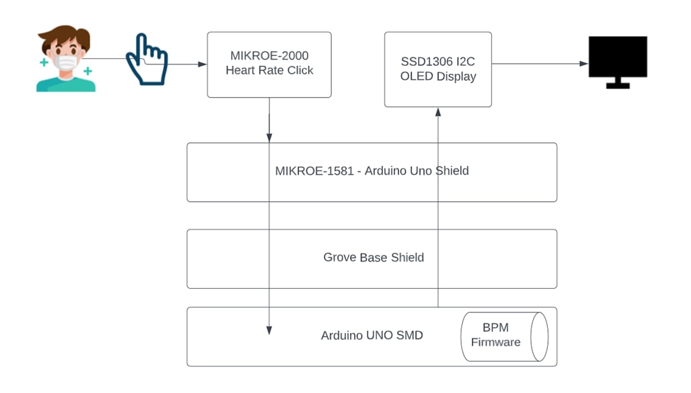
- The interface is a touch sensor that when a finger is placed over the device a heart rate value can be detected.
- This value is used along with other values read over a minute to calculate the Beats per Minute of the patent.
- Once a BPM is calculated it will be displayed on a screen.
Block diagram
The following block diagram, shows the connections of this stacked prototype.

Wiring Diagram
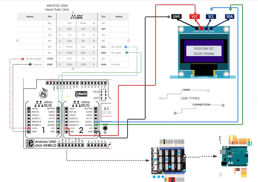
- The following diagram, Shows the components used to build my prototype.
- Uno SMD MCU
- Grove Uno Base Shield (stacked)
- MIKROE Uno Shield, (stacked)
- MIKROE-2000 Heart Rate Click (stacked onto mikroBUS 1)
- SSD1306 OLED Display (wired to mikroBUS 2)
- The two shields are stacked onto the UNO. With there pins matched up to the Header pins on the UNO,
- The MIKROE-2000 Heart Rate Click is stacked onto the stacked onto mikroBUS 1, of the MIKROE Uno Shield. The connections used are depicted with a DOTTED line.
- The SSD1306 OLED Display is wired to the mikroBUS 2 of the MIKROE Uno Shield. The wiring is depicted with a SOLID
- There is only 4 wires used for this build. The rest of the Build involves stacking the components onto each other and assuring the pins are lined up on there headers.

Software Design
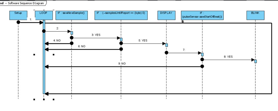
This section shows the Logic of the flow of the Firmware
UML Sequence Diagram

Libraries
This section list the Third Party Arduino supported libraries used in the firmware
Arduino-MAX30100 Library on GitHub
https://github.com/adafruit/Adafruit_SSD1306 (SSD1306 library)
https://github.com/adafruit/Adafruit-GFX-Library (GFX library)
I2C two wire library “wire.h”
Summary & Conclusions
I was able to find the Arduino-MAX30100 library on the internet.
REFERENCES
Most of the images in the diagrams were taken off the internet
All the Diagrams were produced using LucidChart
