


This is my final project submission for the Think ON Design Challenge. The name of the project is Smart N' Safe and it is a Smart Home Device
Quick Jump Links
Video Link https://youtu.be/mDQ3nHwQaZs
Aim: The aim of this project is to design a Smart Home system with the help of an RSL10-SENSE-DB-GEVK, which collects data from the onboard sensors, and then sends it to the cloud for processing, and controls various processes in the house (ex. Lighting, Air Conditioning, etc)
Methodology: For this project, a test bench setup was created to program the RSL10, and connect it to various IoT platforms to process and control the various systems around the house.
Firstly, the RSL10 board would collect data and send it to the mobile app for Atmosphere IoT.
The data collected would be compared to certain set points.
Depending on the setpoints, the Atmosphere IoT app will then send the data to IFTTT, which then, in turn, will be used to trigger a set of buttons on the Adafruit IO Site.
Depending on the buttons triggered on Adafruit IO, the data is sent to the ESP32 connected on home Wi-Fi, to control the devices set up on the test bench.
Components Required:
1x RSL10-SENSE-DB-GEVK
1x Segger J-Link LITE Cortex-M Debugger
1x NodeMCU ESP32
1x Red LED (to simulate Alarm Scenario)
1x Buzzer (to simulate Alarm Scenario)
1x White LED (to simulate Lighting Scenario)
1x Servo Motor (to simulate Temperature and Humidity Scenario[open/close window])
2x Breadboard
1x 3D printer (for 3D printed components)
2x 330ohm resistor
Connecting Wires
Procedure:
The first step is to open the Atmosphere IoT platform.
After creating a project, and selecting the RSL10-SENSE-GEVK, head over to the Embedded tab, and place a few components as shown in Fig1 from the Element Toolbox.
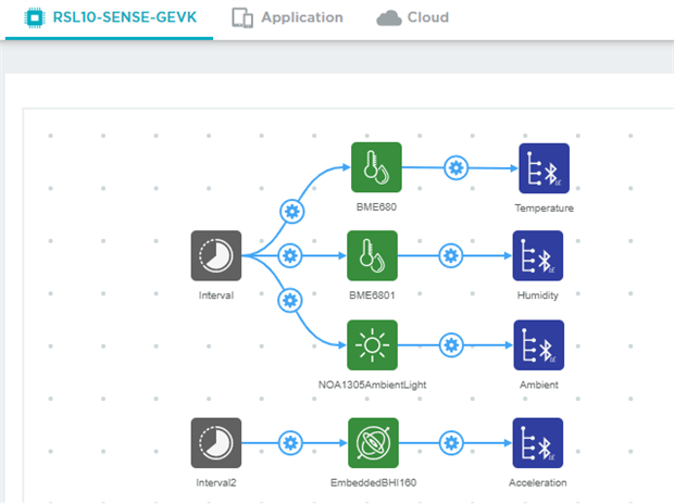
Fig1: Embedded Tab of Atmosphere IoT
From Fig1., the three sensors used are the BME680 (environmental sensor), NOA1305 (Ambient Light Sensor) and the BHI160 (3 axis Accelerometer).
These are programmed to read data every 900,000 milliseconds (15 minutes) with the help of the Interval Element, which then sends the data to the app with the help of the BLE GATT Element.
Heading over to the Application Tab, for the next step.

Fig 2. Application Tab of Project
From Fig.2: The Interval3 requests data from the BLE GATT characteristics which are connected in the Embedded Tab every 15 minutes.
I will explain the components in this tab from top to bottom.
Firstly, the Interval3 requests temperature data. This data is sent to the TempLabel to display on the app, and to an Expression element.
The other input of the Expression element is the Setpoint set in the app, which is the TempControl Slider.
The Expression element compares the Setpoint and the Measured Value.
Depending on whether the value of the condition is Not Zero or Zero, the Fan/AC is triggered ON or OFF respectively.
The turning ON/OFF of the Fan/AC is done with the help of the Webhook Element, which is only triggered if the respective condition is true, and sends data to an IFTTT webhook which in turn triggers a set of buttons on Adafruit IO (more on this later)
The Interval3 requests for the Humidity Data from the BLE GATT Characteristics and then display the values on the App Interface (HumLabel)
The Interval3 requests for the Ambient Light Data from the BLE GATT Characteristics and is sent to display on the App (AmbLabel) and is also sent to two condition elements.
The ambient light data is compared to set points (which I have set according to my lighting requirements and preferences in my room), to set the light ON/OFF in the room.
Depending on which condition is triggered, BrightCond turns the lights OFF, and DimCond turns the lights ON. The controlling of the lights is once again done using Webhooks, IFTTT, and Adafruit.
The last part of the Application Tab is the Motion Detect part.
The SetAlarm button can be toggled from the Atmosphere IoT App. The reason for this button is so that I can trigger the alarms whenever I require so that it does not have to be on all the time.
The button is connected to the Interval1, which requests data every 2000 milliseconds(2 seconds) from the BLE GATT characteristics for Acceleration data. This is connected to the MotionDetect condition. The use of this condition is to trigger whenever any acceleration is detected (i.e whenever acceleration is not zero). When the condition is triggered it sends data to IFTTT and the Adafruit IO.
The next part is the design of the App View
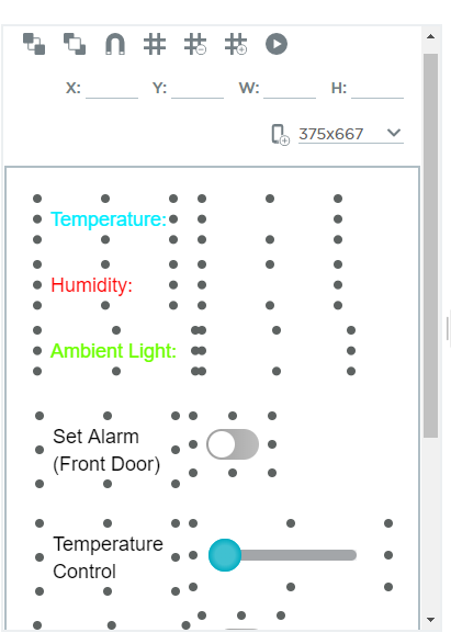
Fig3. Design of App Interface for Mobile App
From Fig3.
This is the application design interface for the app view, which is available in the Application Tab. This is a simple drag and drop interface, and the elements can be placed as required.
Various screen sizes can be chosen depending on your requirements, I have chosen the iPhone 7 screen size as seen from Fig4.
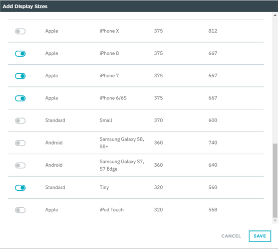
Fig4. Choosing Screen Sizes depending on Requirements.
The next step is to create the Feeds for Adafruit IO, as seen from Fig5
The feed values are changed, and the corresponding value changes in the dashboard.
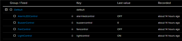
Fig5. Creating Feeds of Adafruit IO
The next step is to create a Dashboard, create the buttons, and to set values to control devices, as seen from Fig6.
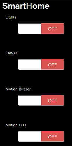
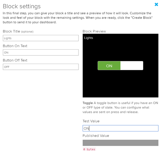
Fig6. SmartHome Dashboard, Block Settings of Lights Block
From Fig6.
Whenever the Feed value changes, the value on the dashboard changes, and sent to any device connected to the dashboard and MQTT subscription (more on this later)
The next step of the project is to use the data to trigger smart home devices. To control the devices, Adafruit IO is used, and to bridge the two platforms, the IFTTT platform was used.
For the creation of the bridge, we need to create a new applet, which can be done as showed in Fig7.
Fig7. IFTTT platform Applet Creation
From Fig. 7, The "This" part is a webhook.
If the webhook receives a Get or Post request, it triggers the next action
The "That" part is the Adafruit IO. It sends data to the Adafruit IO Feed to trigger an action.
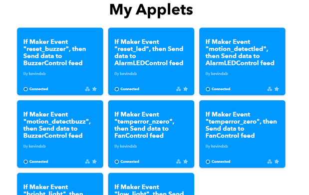
Fig8. Applets created for this project
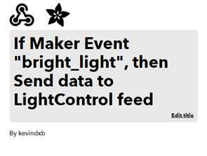

Fig9. bright_light Applet Settings
From Fig. 9 (for example, we take one applet created)
The process flow of the bright_light applet is as follows:
From the Atmosphere IoT application, the data is collected by the BLE GATT characteristics at 15 minutes intervals. Depending on the condition satisfied, the specified webhook gets triggered. In this case, whenever the value goes above the threshold, this applet is triggered and data is sent to the Adafruit Feed. Once the webhook is triggered the button value changes depending on the webhook.
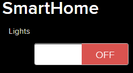
Fig10. The Button status before and after being triggered by the bright_light Applet respectively
The next part is to connect the ESP32 to Adafruit and use it to control the test bench setup devices.
Using the Arduino IDE, the ESP32 is programmed.
The Serial Monitor of Arduino IDE is shown in Fig.11
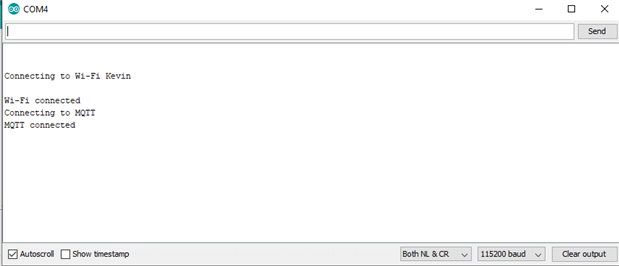
Fig11. The ESP32 connection with Wi-Fi and MQTT to Adafruit IO is made
The software implementation is completed, now its time to have a look at the hardware part.
For this, I have created a test bench setup to simulate and test out the working of the software implementation part.
The test bench included the following:
Red LED (to simulate Alarm Motion Condition)
Buzzer (to simulate Alarm Motion Condition)
White LED (to simulate bright/dim Light Condition)
Servo (to simulate Temperature Condition to Open/Close windows)
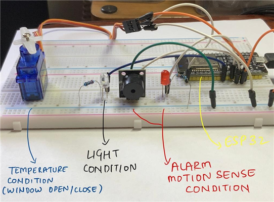
Fig12. Test Bench Setup
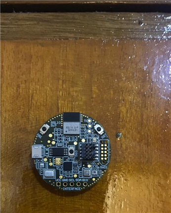

Fig13. Placement of RSL10 board on the top right part of the door
The test setup works in the following way:
- When the Alarms have been set up on the app for the motion detection, if the sensor detects a change in acceleration on the door, it sends a request to the Webhook, which in turn triggers the Adafruit IO Feed, and that triggers the Red LED and the Buzzer.
- When the Ambient Light value sensed by the device reaches thresholds:
If the ambient light is low, the device sends a signal to the App and then to Adafruit IO to trigger the white LED on.
If the ambient light is high, the device sends a signal to turn off the white LED.
- If the temperature or humidity reaches the set threshold values:
If the room is hot or has high humidity, it sends a signal to open the windows (shown by Servo rotation to mimic Opening of the window)
If the room is cold, it sends a signal to close the windows. (implied by Servo rotation)
When these above values change to ON or OFF, the Adafruit IO dashboard also changes respectively.
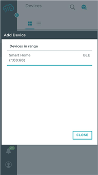

Fig14. Connecting to RSL10 from Atmosphere IoT app

Fig15. App View as designed on the Atmosphere Platform
Observations:
The following conditions and observations are below:
When the ambient light value is at a low value, the white LED turns on, as shown in Fig16.
To simulate the low light scenario, I covered the board with my hand and set the Interval in the app to 1000 ms just for demonstration purposes.
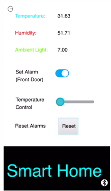
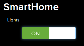

Fig16. Low Ambient Light
Similarly, the high ambient light condition turns OFF the white LED.


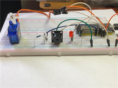
Fig17. High Ambient Light
When the app receives a high humidity value, it causes the window to open, and once the humidity goes to a lower value below the setpoint, it turns servo back to normal position.
To simulate this scenario, I blew on the sensor to increase humidity for demonstration purposes.

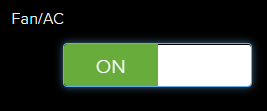
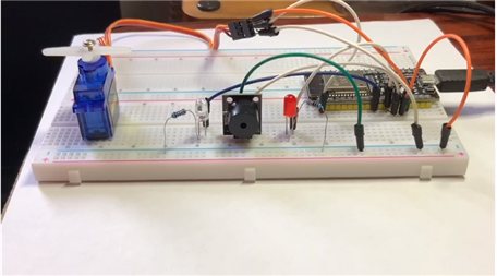
Fig18. High Humidity Scenario, servo position changed to show window opening.
Similarly, the low humidity scenario.


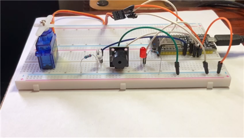
Fig19. Low Humidity Scenario, servo back to start position
The next test is motion detection, firstly the Alarm has to be set using the App. Once the alarm is set, the BLE GATT characteristics get the data and compare it to check any change in acceleration (i.e door movement)
If any motion is detected( acc!=0), the Red LED and Buzzer get triggered ON.

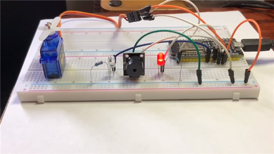
Fig20. The alarm is set on the app, Motion has been detected and Red LED and Buzzer On.
I designed a 3D printed model, but could not print it out.
The hole at the top is to place the RSL10 board so that it can be exposed to environmental conditions required to be sensed and not give faulty readings.
The small rectangular cut-out which can be seen at the bottom is to provide access to a switch to turn ON/OFF the device.
The bottom partition is for attaching a LiPo battery to increase the time the device can be used without requiring maintenance.
The 3D print STL file has been attached.

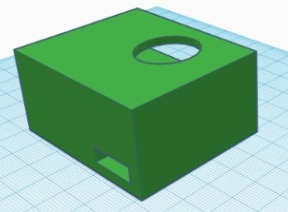
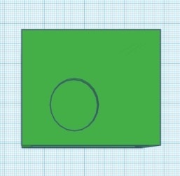
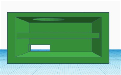
Fig21. Perspective Views, Top View, Front View
This is the end of my software and hardware implementation and explanation.
The video demonstration with an explanation is here:
Video Link https://youtu.be/mDQ3nHwQaZs
Conclusion:
The RSL10-SENSE-DB-GEVK is a powerful board. The low power consumption and a wide variety of sensors make it a great board to prototype and use. The tutorials that were available to learn to prototype the board was lacking and it was a bit challenging to reach this final project outcome.
Over the course of this challenge I have learned the following:
- Prototyping with the RSL10-SENSE-DB-GEVK
- Using the Atmosphere IoT platform to retrieve data from the onboard sensors and send them to the cloud.
- Triggering the devices with the help of IFTTT and Adafruit IO
- A bit of 3D printing (even though I was not able to print the part out and test it)
This project was definitely challenging (being my first challenge in this community) and fun to participate in.
I would like to thank ON Semiconductor and Element14 for giving me the opportunity to participate in this challenge.
Future Scope:
1) To replace the Test Bench setup, and use it to control the actual processes in the house, like the Lighting, AC, etc. (None of the devices in my house right now are IoT capable, so this will take a while to do)
2) To design and print a custom enclosure for the device. (This will be possible to do once my university opens from the shutdown, and I have access to 3D printing equipment available in university)
3) To replace the coin cell powering the board with a LiPo battery so that it can be turned on for longer without maintenance requirement.
----------------------------------------------------------------------------- End of Project -----------------------------------------------------------------------------
I hope this post finds everyone safe and healthy during this time of social distancing.
Thanks for reading my project submission.
If you do have any suggestions, feel free to comment on any changes that I should make to this smart home device for future implementation.
TL;DR. Have a look at my video demonstration which explains all the processes and implementation and working of this project.
Video Link https://youtu.be/mDQ3nHwQaZs