Mechanical design
In this blog, I will try to explain the considerations I made to come up with the final mechanical design. The criteria the design must met are
- The cables must be winded inside the robot. It’s not desirable to have cables hanging around as I saw I many other 2D plotters that uses an external weight to counteract the weight of the movable part (like here for example). Consequently, I need to have two spools to wind the cables
- A typical photovoltaic system is made of different modules installed in closed proximity. Each module as an aluminum frame slightly elevated from the glass surface that protects the PV cells. Also, limit switches should not be affected by the frame. There are also some other components that ties the PV module to the roof. Finally, there is typically a gap between the modules. Rullit must be able to “climb over” all these obstacles

- Rullit is going to operate on a sloping surface, and this creates some problems for the water tank. To simplify refill operations, it is probably better to have the water tank levelled, so I can fill it up even when the robot is already in place
Sizing of the motors
Let’s make an approximate calculation of the torque required to move the robot on a sloping surface. First, I need to make a guess about the robot weight. The heaviest components of the robot are
- The water. Since I want Rullit to be able to operate autonomously on large installations, the water reservoir must be significant. Five liters (or 5 kg) of water should be sufficient
- The battery. I’m going to use a lead battery, which weighs about 1.5 kg
With just water and battery, we reach a weigh of 6.5 kg. Let’s stay on the safe side and make a rough estimation of a total weigh of 10 kg
The robot is going to move on a chute, so the actual force the motors must be able to handle can be calculate by means of the following formulas


Fpx is equal to

Next step is the calculation of the required motor torque. Torque is defined as rotational force at a distance from the rotational axis. Torque is just as important, if not more important, than the horsepower of a motor. Horsepower is how fast the work can be done and is calculated with torque multiplied by speed. In other words, torque is the capacity to do the work, and power is the speed at which the work can be done. Torque has 2 main components: load torque and acceleration torque. Load torque is the amount of torque constantly required for application and includes friction load and gravitational load.
For a pulley drive application, the load torque calculation is straight forward. We need to generate a force at some distance away from the motor shaft (definition of torque). This can be calculated by multiplying force (F) by the rotation radius (r). To move the load (blue box), the motor must generate more torque than this value.

To calculate load torque, multiply the force (F) by the distance away from the rotational axis, which is the radius of the pulley (r). In our case, the force exerted by the load (i.e. the robot itself) is equal to 70 Newtons. Assuming that the radius of the spool is 5 cm, then the required torque for the application is 70 N x 0.05 m = 3,5 Nm. Typically, a safety factor is used so that the motor generates more torque than required to accommodate any inaccuracies in variables used for calculation.
Here's the formula to calculate load torque for a pulley drive with all the variables:

At this moment, it’s difficult to evaluate the amount of torque required to “beat” the friction. In the optimal case (no friction), the required torque is

To stay on the safe side, I will double the torque value and select a motor with a torque of at least 7 Nm
Unfortunately I only found these motors with gears that seems suitable for my application in terms of size (and cost as well...). The only drawback id that they are rated for a torque of 40 kg*cm, which is about 4 Nm. I will use these motors. In case the torque is not enough, I can play with pulleys diameters

The reduction box contains a worm screw, which is good since it makes Rullit intrinsically safe: in case of low battery or any other failure, the motors are getting stuck and prevent Rullit from falling from the roof

The wheels
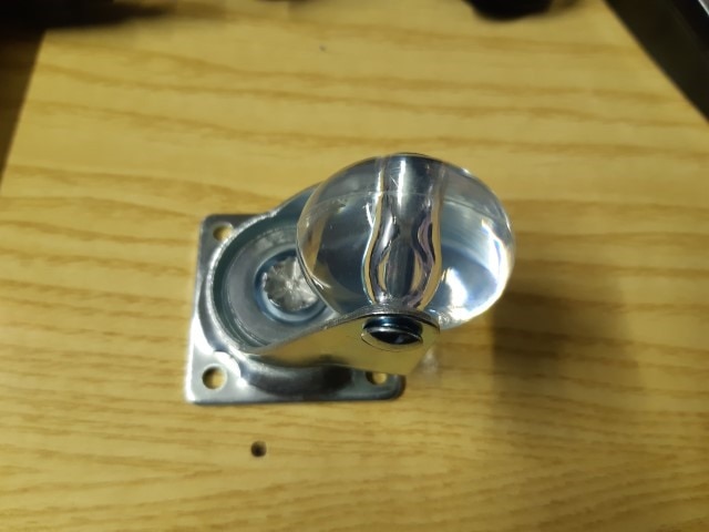
Wheels are not supposed to provide directionality or traction to the robot. Their only purpose is to reduce the friction between the robot and the PV module’s surface. For these reasons, I selected some caster wheels from the local DIY shop. They can handle more than 40 kg each, so they are probably overkilled for this application. However, the selection was limited by the minim wheel diameter needed to overcome the slot between the PV modules

Limit switches
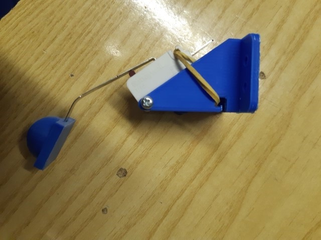
Four limit switches are installed to prevent the robot from falling down the PV panels. The mechanical travel of any limit switch is too limited to compensate for the height of the PV panel frame. So, I devised a swinging support that tries to keep the limit switch as close as possible to the surface even when the robot is climbing over the PV panel frame
Here is a diagram of the supports for the limit switches.

This is one of the limit switches mounted on its support. The switch is pushed against the PV module surface by a rubber band. With this configuration, the travel of the limit switched is drastically increased. I also added a sort of "pad" to prevent the limit switch to be triggered by a gap between the PV modules

The roller
To clean the surface, I will use a paint roller you can buy in any DIY shop. I will use a DC motor with reduction gear. As far as I can see, I just need an adapter to link the motor shaft with the hole in the paint roller
The DC motor for the paint roller is slightly smaller, to save weight and space. Because the DFRobot board has only two motor outputs, the roller motor will be switched on and off by means of an external relay module

Mechanics overview
With these constraints in mind, the components will be deployed as shown in diagram below

|
Prev: Project description |
Next: Wiring |


-

robogary
-
Cancel
-
Vote Up
0
Vote Down
-
-
Sign in to reply
-
More
-
Cancel
-

amgalbu
in reply to robogary
-
Cancel
-
Vote Up
0
Vote Down
-
-
Sign in to reply
-
More
-
Cancel
Comment-

amgalbu
in reply to robogary
-
Cancel
-
Vote Up
0
Vote Down
-
-
Sign in to reply
-
More
-
Cancel
Children