In this post, I will write about the user interface and remote control application developed as part of this challenge
Local display
Rullit has a local OLED display with a resolution of 128x32 pixels. The display shows the information shown in picture below

Namely
- Limit switches status (left, front, aft and right). When a limit switch has detected an edge, the corresponding letter is printed with white background
- Roller motor status, either on (text background is white) or off
- Solenoid valve status, either on (text background is white) or off
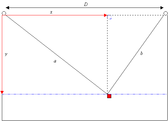
- Current estimated (x,y) position
- Current estimated ropes length (a and b, as shown in diagram below)
- Current PWM values for left and right motors, from -100% to +100%. The sign indicates the versus of rotation
- Current application status. Possible values are
- StartUp: application is initializing
- Moving: robot is cleaning PV module
- Completed: cleaning process has been completed and robot has reached home position
- Current mode (manual or automatic)
- Last command received from the remote control application
- Bluetooth status (connected or disconnected)
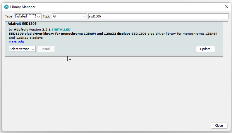
To implement the local display, I imported library SSD1306 from Adafruit. Library has a lot of useful examples that shows all the functionalities of the display
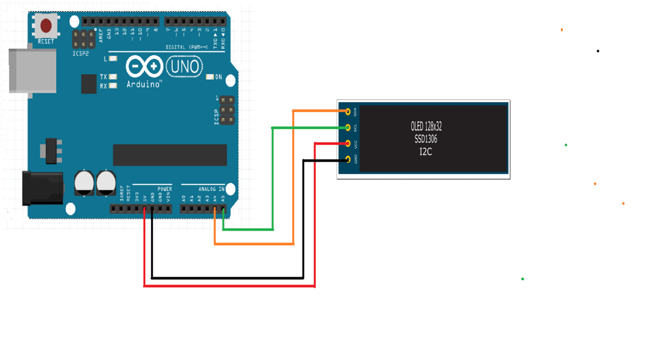
Display has 4 pins (Vcc, GND, SDA and SCL), which have been connected to the following pins

I created a class Display to manage the display and optimize the update of the screen content. You can refer to files display.cpp and display.h for all details
Remote control
To control the robot remotely, I developed an Android app that connects on a Bluetooth channel to Arduino. On the robot, I installed a Bluesmirf board. This board is now obsolete, but it can easily be replaced by a more up-to-date board that implements the Bluetooth serial-replacement profile
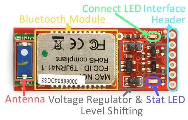
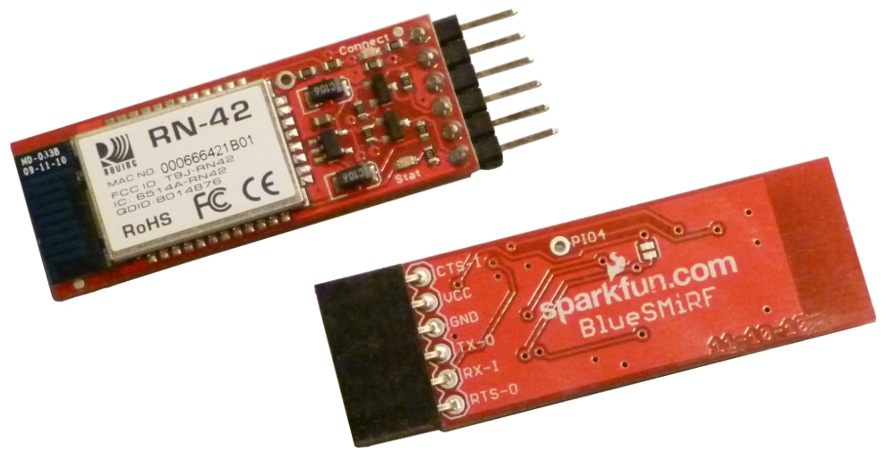
Connection are extremely easy, because the Bluesmirf module supports input voltages on all pins up to 6 volts. So I can use the 5V of the Arduino board and connect TX and RX pins to Arduino pins with no needs for an external voltage divider
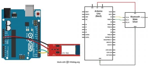
To communicate with the Bluesmirf module, I imported the SoftwareSerial library. This library implements an asynchronous serial port on any Arduino pin. In my case, I am going to use pin 2 and 3
The Bluesmirf has a default baudrate of 115200. SoftwareSerial has some issues at such high speeds, so I need to reduce baudrate to 9600. This is accomplished in the init() function of the Bluesmirf class (see bluesmirf.cpp file). The init() function performs the following tasks
- Initialize the SoftwareSerial port to the Bluesmirf’s default baudrate
- Switch from data mode command mode, by sending the string “$$$”
- Send the command to set baudrate to 9600
- Send the command to set Bluetooth slave mode (this is not strictly required, since this is the Bluesmirf’s default mode
- Switch from command mode back to data mode by sending the string “---”
 _bluetooth.begin(115200);  // The Bluetooth Mate defaults to 115200bps
 _bluetooth.print("$$$");  // Print three times individually
 delay(100);  // Short delay, wait for the Mate to send back CMD

 _bluetooth.println("U,9600,N");  // Temporarily Change the baudrate to 9600, no parity
 // 115200 can be too fast at times for NewSoftSerial to relay the data reliably

 _bluetooth.begin(9600);  // Start bluetooth serial at 9600
 _bluetooth.print("$$$");  // Print three times individually
 delay(100);  // Short delay, wait for the Mate to send back CMD
 _bluetooth.println("SM,0");
 delay(100);
 _bluetooth.println("---");
 delay (100);
I implemented a protocol where the Android app continuously sends commands and the Arduino board continuously replies with its current status. The request is made of the following bytes
‘$’: Start-of-frame character
<Mode>: 0=automatic, 1=manual. In manual mode, user can drive the robot up, down, left or right
<Command>: the command to execute.
In automatic mode, the supported commands are
Start: start the automatic cleaning procedure
Stop: interrupts the cleaning process
In manual mode, the supported commands are
LeftUnwind
LeftWind
RightUnwind
RightWind
When no command has to be executed, this field is 0
<Outputs>: output status to set. This is a bits field, where the bits have the following meanings
Bit 0: 1=start motor roller, 0=stop motor roller
Bit 1: 1=Open valve, 0=close valve
‘#’: End-of-frame character
The response has the following fields
‘$’: Start-of-frame character
<Application status>: 0=automatic, 1=manual. In manual mode, user can drive the robot up, down, left or right
<Switches>: Status of the limit switches. This is a bits field, where the bits have the following meanings
Bit 0: status of the left limit switch
Bit 1: status of the front limit switch
Bit 2: status of the rear limit switch
Bit 3: status of the right limit switch
<Outputs>: current status of the outputs. This is a bits field, where the bits have the following meanings
Bit 0: 1= motor roller running, 0=motor roller stopped
Bit 1: 1= valve open, 0=valve closed
<X>: current X position, represented on two bytes (first byte is the MSB)
<Y>: current Y position, represented on two bytes (first byte is the MSB)
<a>: current length of section “a” of the rope, represented on two bytes (first byte is the MSB)
<b>: current length of section “b” of the rope, represented on two bytes (first byte is the MSB)
<pwmLeft>: current PWM value for the left motor
<pwmRight>: current PWM value for the right motor
‘#’: End-of-frame character
All the logic to manage the communication protocol is implemented in class BlueSmirf (see bluesmirf.h and bluesmirf.cpp)
User can interact with the robot by means of an Android app, whose interface is shown in picture below
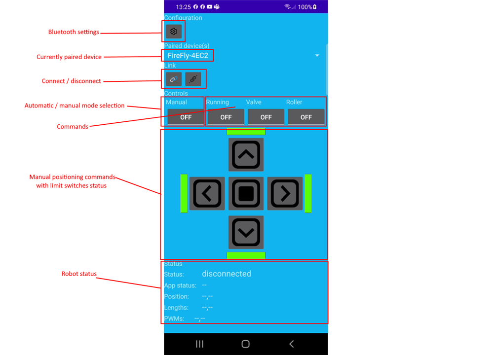
For the Android app, I got inspiration from Jeff Boody's BlueSmirf demo (available here)
|
Prev: The software (update) |
Next: Final demo |

