


After some preliminary tests, I realized the approach I followed was not to best one, so I made some correction to the Rullit’s control software
Problem
There is basically one major problem in the implementation I talked about in my previous post [link]: because of the low threshold in PWM values (required to prevent motors from stalling), motors are switched on and off very rapidly. This causes many current peaks. In general, I noticed that every time the motor is started under load, there is a current peak. Since the L298P (the component the DFRobot DRI0017 is built on) is rated for current peaks up to 2.5A, I set the overcurrent protection on my power bench to this value and checked whether in any condition this value is exceeded
My solution
The solution I chose to implement is to change the path of the robot. I am going to keep the left motor stopped and I will drive the right motor until one of the limit switches is triggered. The resulting path is something like this

This solutions has two advantages
- it does not require a precise control of the motor speed, because all the logic is controller by limit switches
- it does require any knowledge about the size of the PV modules, because again all the logic is controller by limit switches
Depending on the limit switch that has triggered, I am taking different actions
I created a function (stepMotor) to
void stepMotor(int motor, int dir, int perc)
{
 Serial.print("stepMotor ");
 Serial.print((motor == LeftMotor)? "LEFT " : "RIGHT ");
 Serial.print((dir == WIND_DIR)? "WIND " : "UNWIND ");

 Serial.print(perc);
 Serial.print("%");
 Serial.println();

 moveMotor(motor, dir, perc);
 delay(PATH_STEP_MS);
 stopMotor(motor);

 Serial.print("stepMotor completed");
}
This function winds or unwinds left or right rope of a fixed length
Left limit switch
When the left limit switch is triggered, the right rope is winded to move the robot back at safety distance from the edge, then the left rope is unwinded to let Rullit clean the adjacent slice of PV module.
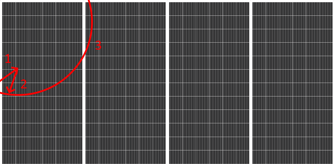
Finally, the right motor is started in order to wind the right rope and move the robot toward the top of the PV module
void handleLeftLimit()
{
 Serial.println(">>> LEFT LIMIT");
 stepMotor(RightMotor, WIND_DIR, WIND_PERC);
 stepMotor(LeftMotor, UNWIND_DIR , WIND_PERC);

 Serial.println("moveMotor RIGHT WIND");
 moveMotor(RightMotor, WIND_DIR, WIND_PERC);
}
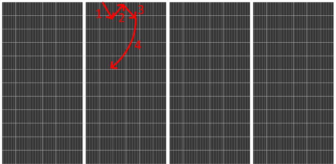
Bottom limit switch
When the bottom limit switch is triggered, the left and right motor are winded to move the robot back at safety distance from the edge, then the left motor is unwinded twice to let Rullit clean the adjacent slice of PV module.

Finally, the right motor is started in order to wind the right rope and move the robot toward the top of the PV module
void handleBottomLimit()
{
 Serial.println(">>> BOTTOM LIMIT");
 stepMotor(LeftMotor, WIND_DIR, WIND_PERC);
 stepMotor(RightMotor, WIND_DIR, WIND_PERC);
 stepMotor(LeftMotor, UNWIND_DIR, WIND_PERC);
 stepMotor(LeftMotor, UNWIND_DIR, WIND_PERC);

 Serial.println("moveMotor RIGHT WIND");
 moveMotor(RightMotor, WIND_DIR, WIND_PERC);
}
Top limit switch
When the top limit switch is triggered, the left rope is unwinded and right rope is winded to move the robot back at safety distance from the edge, then the left motor is unwinded twice to let Rullit clean the adjacent slice of PV module.
Finally, the right motor is started in order to unwind the right rope and move the robot toward the top of the PV module
void handleTopLimit()
{
 Serial.println(">>> TOP LIMIT");
 stepMotor(LeftMotor, UNWIND_DIR, WIND_PERC);
 stepMotor(RightMotor, WIND_DIR, WIND_PERC);
 stepMotor(LeftMotor, UNWIND_DIR, WIND_PERC);

 Serial.println("moveMotor RIGHT UNWIND");
 moveMotor(RightMotor, UNWIND_DIR, WIND_PERC);
}
Right limit switch
When the right limit switch is triggered, the right rope is unwinded to move the robot back at safety distance from the edge, then the left motor is unwinded twice to let Rullit clean the adjacent slice of PV module.
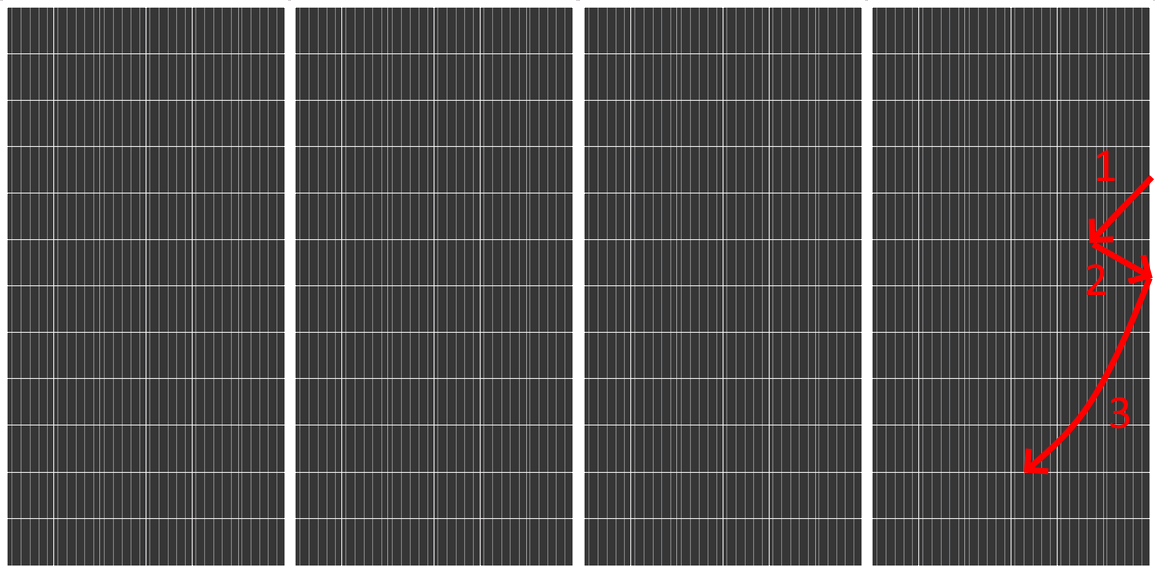
Finally, the right motor is started in order to unwind the right rope and move the robot toward the top of the PV module
void handleRightLimit()
{
 Serial.println(">>> RIGHT LIMIT");
 stepMotor(RightMotor, UNWIND_DIR, WIND_PERC);
 stepMotor(LeftMotor, UNWIND_DIR, WIND_PERC);

 Serial.println("moveMotor RIGHT UNWIND");
 moveMotor(RightMotor, UNWIND_DIR, WIND_PERC);
}
Clean completion
The clean process is completed when right and bottom switch are triggered less than 15 seconds apart. This means we are enough closed to the bottom right corner of PV modules
Soft start
As a further protection against current peaks, I will implement a soft-start algorithm, where the motor are started with increasing PWM values, according to a fixed sequence. Currently, I am experimenting with this sequence
10%
20%
50%
100%
Each step in the sequence last 500 ms, so it takes about 2 seconds to go from 0 to the nominal RPMs
void moveMotor(int motorNumber, int dir, float perc)
{
 float sign = +1.0;

 if (motorNumber == LeftMotor) {
  if (dir == WIND_DIR)
   sign = -1.0;
 }
 else {
  if (dir == UNWIND_DIR)
   sign = -1.0;
 }

 for (int i=0; i<sizeof(SoftStartSteps)/sizeof(float); i++)
 {
  moveMotor(motorNumber, sign * SoftStartSteps[i]);
  delay(SOFTSTART_STEPS_DELAY);
 }

 moveMotor(motorNumber, sign * perc);
}
|
Prev: The software |
Next: User interface |

