


The Twist, Turn, and Move Robotics Design Challenge with TE Connectivity
Intro
Mechatronics wasn't even a subject when I was in school, but over the years I have developed a keen interest in this area, and this design challenge is a great opportunity to experiment with some mechatronics ideas.
The components in the kit are quite an eclectic collection of parts that don't lend themselves easily to be used in a single project, so my entry will itself be a collection of several different applications to make better use of kit components. It does not appear that the kit includes complete sets of mating connectors, so the first step is to obtain enough connectors and components to make up mating sets of connectors. I have used many TE Connectivity components over the years, including many AMP connectors and Measurement Specialties sensors. I will likely include use some other Amp connectors in this design challenge since their MTA-100 series is a staple in my projects. This will be the first time I have used an Axicom relay, so this project has already resulted in learning about that company's products.
Here is an animated illustration teaser of Sammy Semaphore saying Hi:

I spent quite a bit of time cataloguing the components supplied in the challenge kit because I want to try to use them all. Here is a comprehensive list of what is in the kit:
|
# |
QTY |
SKU |
MFR Part # |
Description |
Image |
|
1 |
2 |
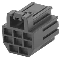
53AJ9498 |
1-2366515-4 |
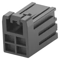
DYNAMIC D1000 SLIM WIRE-TO-WIRE CONNECTOR receptacle : 4 positions, 2 mm pitch key 1 |
|
|
2 |
10 |
53AJ9511 |
2367817-2 |
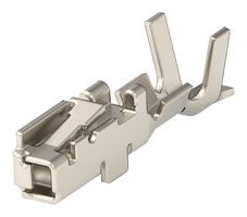
DYNAMIC D1000 SLIM WIRE-TO-WIRE CONNECTOR receptacle - crimp contact |
|
|
3 |
2 |
53AJ9504 |
2-2366515-4 |
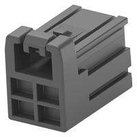
DYNAMIC D1000 SLIM WIRE-TO-WIRE CONNECTOR receptacle : 4 positions, 2 mm pitch key 2 |
|
|
4 |
2 |
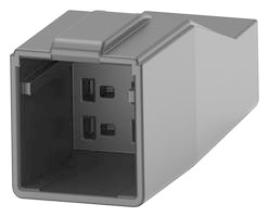
53AJ9501 |
1-2366600-4 |
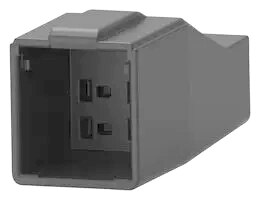
DYNAMIC D1000 SLIM WIRE-TO-WIRE CONNECTOR pin housing : 4 positions, 2 mm pitch key 1 |
|
|
5 |
10 |
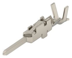
53AJ9515 |
2367819-2 |
DYNAMIC D1000 SLIM WIRE-TO-WIRE CONNECTOR crimp contact pin |
|
|
6 |
2 |
53AJ9507 |
2-2366600-4 |
DYNAMIC D1000 SLIM WIRE-TO-WIRE CONNECTOR pin housing : 4 positions, 2 mm pitch key 2 |
|
|
7 |
1 |
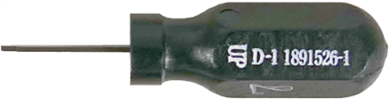
79AH9105 |
1891526-1 |
DYNAMIC D1000 Series Extraction Tool |
|
|
8 |
2 |
53AJ9500 |
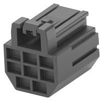
1-2366515-8 |
DYNAMIC D1000 SLIM WIRE-TO-WIRE CONNECTOR receptacle : 8 positions, 2 mm pitch key 1 |
|
|
9 |
2 |
53AJ9506 |
2-2366515-8 |
DYNAMIC D1000 SLIM WIRE-TO-WIRE CONNECTOR receptacle : 8 positions, 2 mm pitch key 2 |
|
|
10 |
2 |
53AJ9503 |
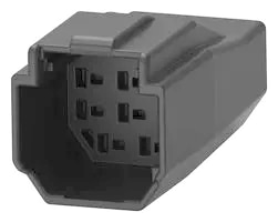
1-2366600-8 |
DYNAMIC D1000 SLIM WIRE-TO-WIRE CONNECTOR pin housing : 8 positions, 2 mm pitch key 1 |
|
|
11 |
2 |
53AJ9509 |
2-2366600-8 |
DYNAMIC D1000 SLIM WIRE-TO-WIRE CONNECTOR pin housing : 8 positions, 2 mm pitch key 2 |
|
|
12 |
1 |
46F314 |
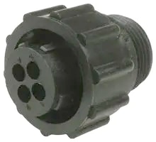
206153-1 |
CPC Series Circular Connector 4 pin contacts |
|
|
13 |
1 |
44F8386 |
206060-1 |
CPC Series Circular Connector 4 receptacle contacts |
|
|
14 |
5 |
50F554 |
201330-1 |
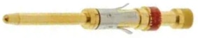
CPC Type II Series 20 AWG pin contact |
|
|
15 |
5 |
50F553 |
201328-1 |
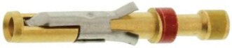
Multimate Type II Series 20 AWG socket contact |
|
|
16 |
1 |
71AJ9362 |
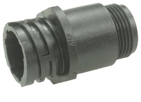
T4011019041-000 |
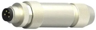
Sensor Connector M8 Male 4 positions Cable mount |
|
|
17 |
1 |
71AJ9360 |
T4010019041-000 |
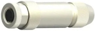
Sensor Connector M8 Female 4 positions Cable mount |
|
|
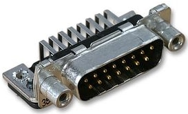
18 |
1 |
39Y8007 |
1-338169-2 |
Amplimite HD-20 Series D Sub Plug 15 pins Through Hole |
|
|
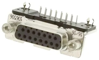
19 |
1 |
39C2868 |
3-106506-2 |
Amplimite HDP Series D Sub Receptacle 15 Through Hole contacts |
|
|
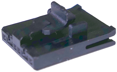
20 |
1 |
76Y5554 |
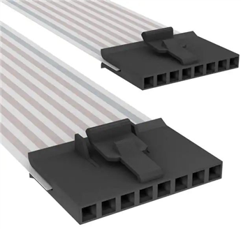
2-487937-6 |
AMPMODU System 50 Series FFC Receptacle 8 position |
|
|
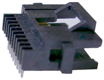
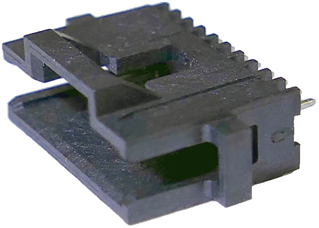
21 |
1 |
40P9901 |
6-104074-0 |
AMPMODU System 50 8 position R/A pin header through hole |
|
|
22 |
1 |
99X6951 |
6-104071-0 |
AMPMODU System 50 8 position straight pin header through hole |
|
|
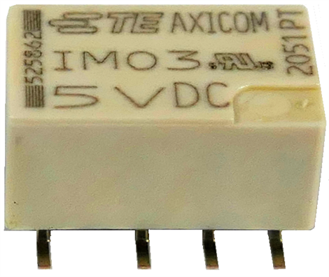
23 |
1 |
19K8733 |
IM03 |
IM Series signal relay DPDT SMT 2A 5V coil 178 ohm |
|
|
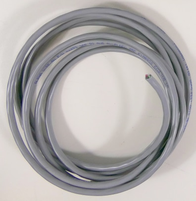
24 |
1 |
89R7072 |
M4473 SL005 |
Alpha Wire 2 pair shielded cable 22 AWG, 9 feet |
|
|
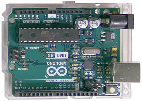
25 |
1 |
78T1601 |
A000066 |
Arduino Uno R3 |
|
|
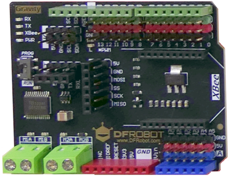
26 |
1 |
DRI0017 |
DRI0017 2x2A Motor Shield |
|
|
|
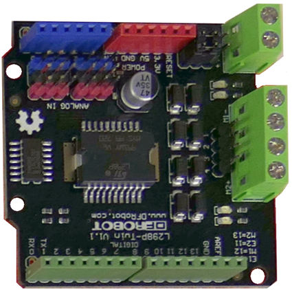
27 |
1 |
DFR0502 |
DFR0502 IO Expansion & Motor Driver Shield |
|

Comments on the Kit
The Dynamic D1000 series connectors include 4 mated pairs of 4 pin housings and 4 mated pairs of 8 pin housings. These connectors need a total of 48 pin contacts and 48 socket contacts, however there are only 10 pins and 10 sockets in the kit, so it isn't enough to populate all the housings. I have ordered more pins and sockets, but have no idea when they might actually arrive.
The AMPMODU System 50 connectors include two 8-pin PCB mount connectors and one FFC cable connector. I do not have the right cable and there is only 1 cable connector in the kit. I also do know how to attach an FFC cable to this connector either so I ordered a complete cable, TE Connectivity part number A9CCA-0806E.
I have no idea when it will arrive either, but I can mount the mating PCB connectors on a PCB in the mean time.
I like to make useful projects, so this collection will include a communications machine, an electromechanical test apparatus and a dynamic showcase.
Applications Descriptions
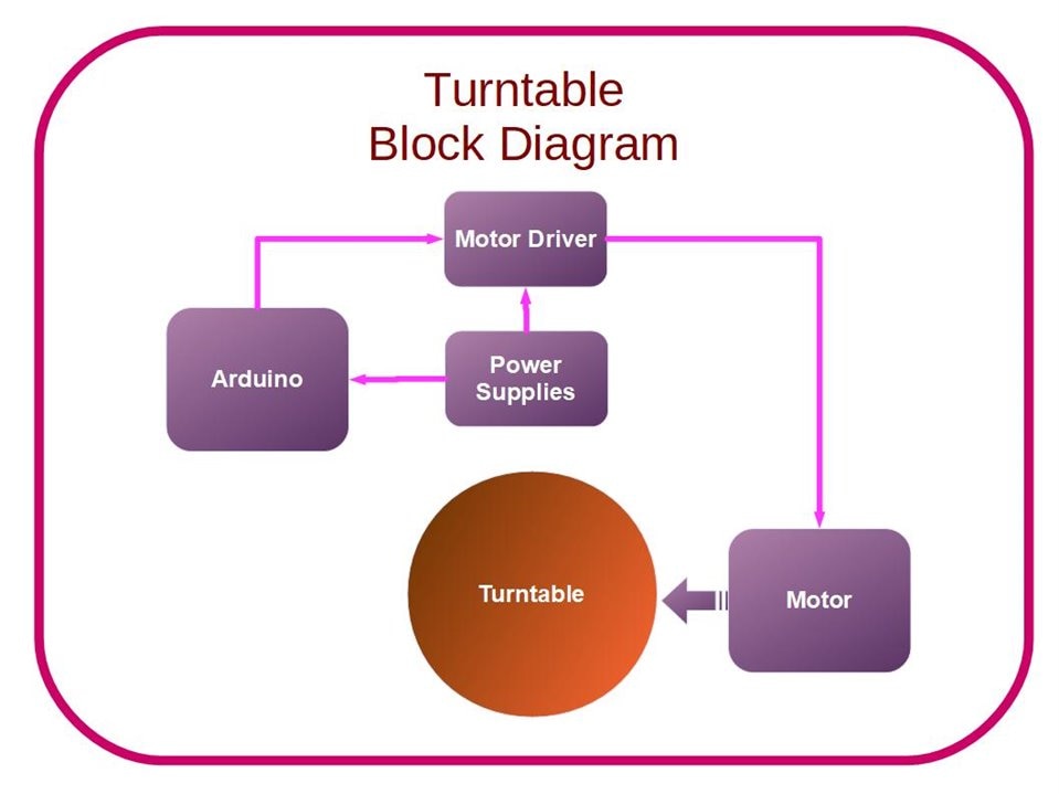
Turn Table
The first system in this project stems from a need to motorize a glass turntable. The turntable is a nice way to exhibit small projects and will be demonstrated. To motorize the turntable I will use a small capstan motor driven by one of the motor controller cards and the Uno. A pot input will be used to control the PWM (speed). The system will be held in place by a 3D printed chassis.
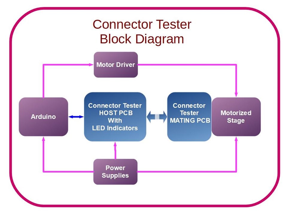
Connector Cycle Tester
The second project will be a cycle tester that connects and disconnects a connector to see how many cycles it takes to wear out the connector. It will use a another motor controller and Uno to drive a scissor jack that translates rotary motion to linear motion, so the connectors can be mated with a straight linear motion. The Arduino will count the number of cycles. LEDs will indicate which pins are still making good contact. An optical limit switch will dictate when the mechanism should reverse.
What would a design challenge be without designing a printed circuit board and this one is no exception, the connector under test will be mounted on a custom PCB which will be used to test the connectors and indicate test status. It will also include connectors to allow other connectors in the kit to be tested with manual insertion, but automated testing and indication. LEDs will indicate when various pins are making contact. The connector being cycled would have each pin tested in sequence to detect any short circuit or any open circuit. The system will be designed such that it can also be used to test complete cables. The Axicom relay will also find a use on the card. Elements of this system will also utilize custom designed 3D printed parts. The intention is to create a fairly complex system with lots of technology, moving parts, connectors in action and lighting effects that converts a useful but fairly boring connector cycle tester into a fun, interesting system to just watch.
Sammy Semaphore
The final system will be a flag semaphore robot called Sammy Semaphore. It will feature a custom semaphore robot that will have 2 arms capable of generating a flag semaphore alphabet. The flag positions will be selectable using ASCII via its serial port. A stretch goal is to use Bluetooth data entry.
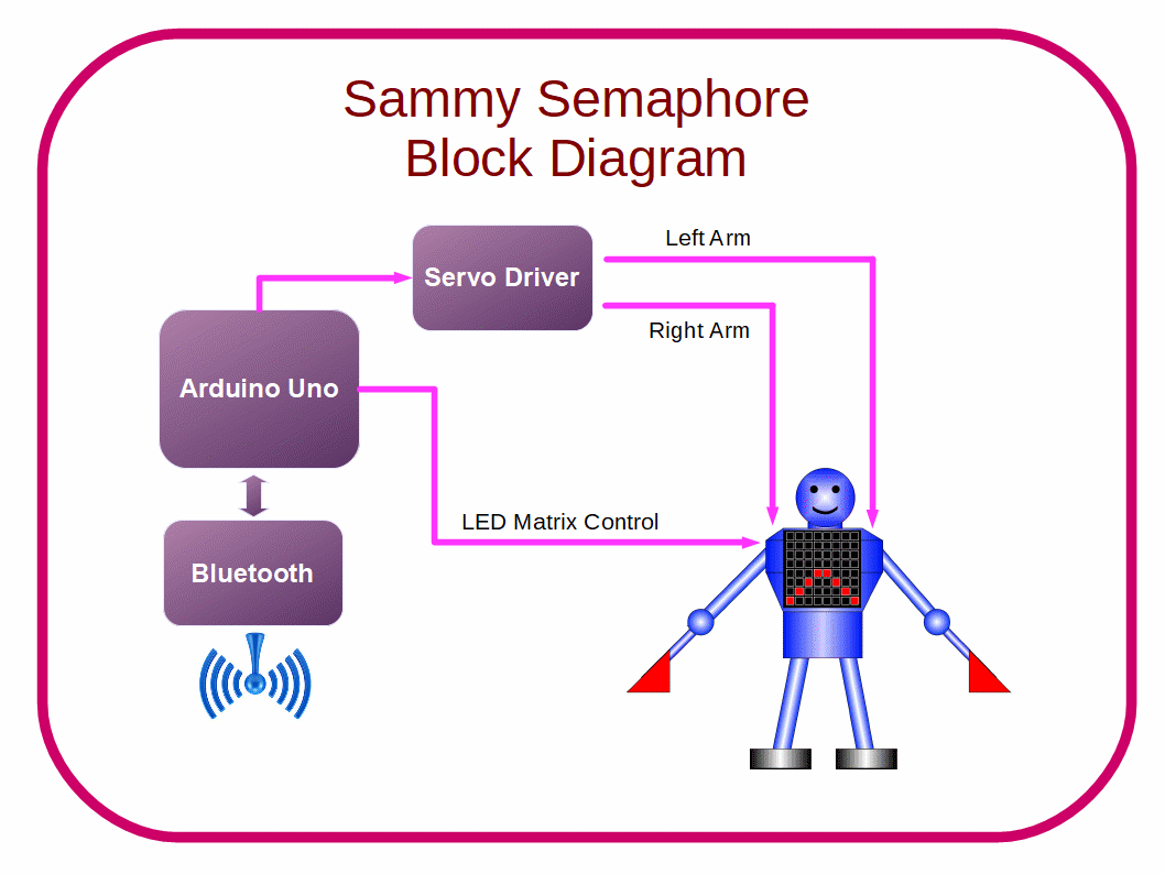
Sammy Semaphore may need an extra Arduino since the kit Uno will be running the connector tester.
Summary & Discussion for Blog 1
To summarize, this project will use 3 custom designed mechatronics systems to showcase the TE Connectivity products that are included in the kit.
The turntable system fills a recurring need I have for better methods to dynamically showcase projects. The connector tester system is an attractive way to implement a connector test instrument, and the last system is a robotic exploration of flag semaphore signaling. To tie the systems together, the turntable will be used to show off Sammy Semaphore and the connector test system.
Relevant Links:
Twist, Turn and Move Design Challenge with TE Robotics
Sammy Semaphore - blog 1
Connector Tester - blog 2
NEO Pixel Display - blog 3
Sammy Semaphore Torso Demo - Blog 4
I Am Sam I Am - Blog 5
TE Connectivity Connector Tester Blog 6
Sammy Semaphore Fully Functional Blog 7


