


1. The Official Challenger Kit

Contents
- Arduino UNO R3 Board
- DFRobot 2x2A Motor Shield for Arduino Twin
- DFRobot Gravity: IO Expansion & Motor Driver Shield
- TE Connectors (so many, can't even name them all)
I really like the Italy Made Arduino UNO R3 board. I have been working on these cheap Arduino UNO clones for such a long time.

2. Testing the 2x2A Motor Shield for Arduino Twin
2.1 Components
- Arduino UNO R3 Board
- DFRobot 2x2A Motor Shield for Arduino Twin
- DC Geared Motor x 2
- Power Source
2.2 Connection
 We need to change the Power Selection Jumper according to our power source. The motors can be powered by external power supply(PWMIN) or VIN from Arduino control board(e.g., UNO).
* The two parallel jumper pins are by default, in VIN. So, if we want to use external power, we need to remove them both from VIN and put them over PWRIN.
In my case, I am using external power source in the Shield, so I had to change two parallel jumpers and put them onto PWRIN as show in the above connection diagram.
The shield uses 4 Pins in total for controlling two motors (2 pins per motor). Pins 10 and 12 for motor M1 and Pins 11 and 13 for motor M2. Pins 10 and 11 are PWM pins and used for controlling the speed of motors.
2.3 Arduino Code for Controlling two motors
Github Code - l298n_motor_control.ino
The code is written so as to control 2 DC Geared motors using the pins 10 and 12 for motor M1 and pins 11 and 13 for motor M2.
2.4 Output
3. Testing the Gravity IO Expansion Shield With Arduino Uno
3.1 Components
- Arduino UNO R3 Board
- DFRobot Gravity: IO Expansion & Motor Driver Shield
- SG90 Servo motor x 2
- MG995 Servo motor x 1
3.2 Connections
Two SG90 servo motor are connected to the pins A0 and A1.
1 MG995 servo motor is connected to pin A5.
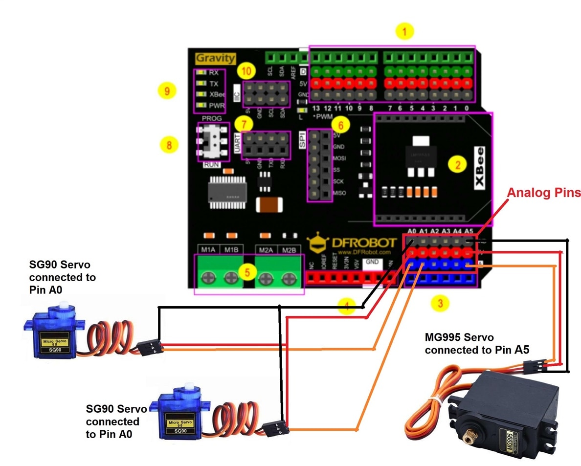
The Analog pins on the shield are attached along with 5V and GND pins in the same order as the Servo motors. It made easier for me to directly put the servo motor connectors into the pins.


3.3 Arduino Code
Github Code - gravity_shield_servo_control.ino
3.4 Output
