


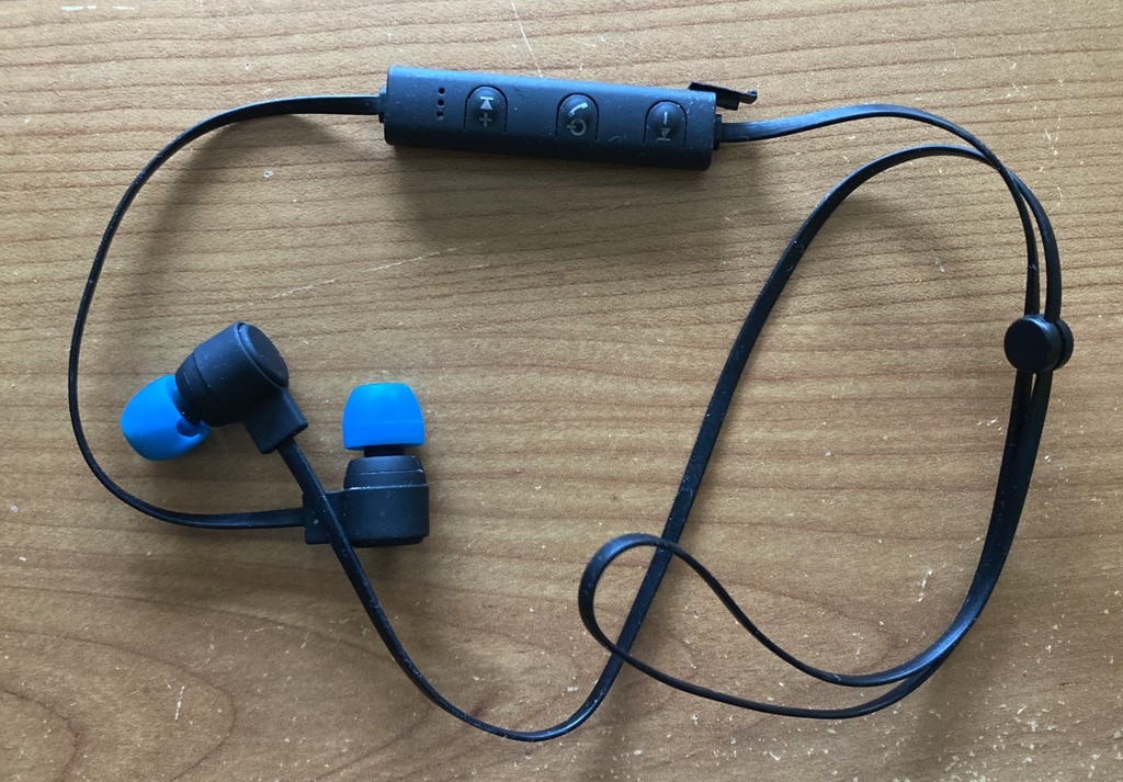
I welcome you to second part of my series as part of Upcycle IoT Design Challenge. In previous blog I described earbuds which I want to upcycle and today I will show them in more details.
Opening Erabuds
Opening is not very hard. Main part plastic consists of two parts and line in the middle is visible. When opening you need to pay attention to battery which is inside. I opened them with sophisticated opening tool – pencil compass, but other sophisticated tools like screwdriver and scissors are also suitable.

Basic parts
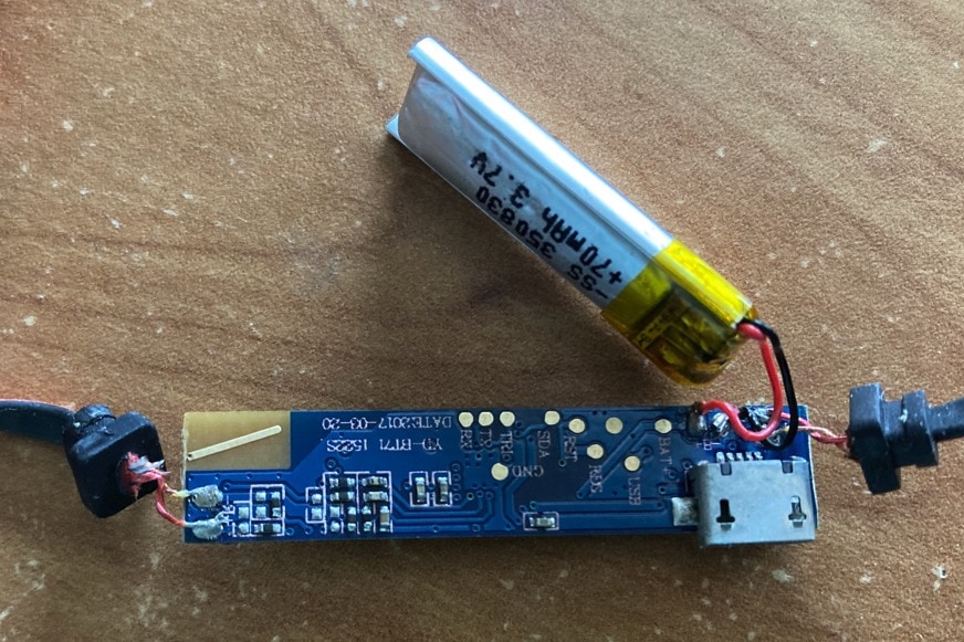
On the device many parts clearly visible:
- Main chip is Airoha AB1522S
- 3 buttons
- 2 LEDs (blue and red)
- Microphone
- PCB antenna in this case (other units has chip antenna)
- Crystal labelled 16 MHz
- USB connector
- Passives
- Test points
Drawing schematics
I originally try reverse engineer schematics in circuit I draw parts to paper and using continuity test mode of digital multimeter I was searching for interconnected parts. It did not produced very good results because parts interfered and measuring continuity of capacitors, coils as well as some “unknown” internls of main chip (like ESD diodes) did not produced reliable result.
Destroying earbuds by multimeter
Even more, I destroyed one unit. Let’s see why. The main SoC work with (at least) three voltages:
- Battery voltage between, approx. 3.7 – 4.2V
- Charger voltage from USB, approx.. 5V
- Main regulated voltage which I measured as 1.6V.
The problem is that continuity meter on multimeter provides voltage to DMM leads and the problem is that while 3V is usually safe, in case when interfering with 1.6V logic of chip, it is not. Even more, when measuring continuite you usually do not worry about polarity, because wire conduct from right to left as well as from left to right. The problem is that DMM measurement voltage is polarized and when reversing I most probably provided not only provided voltage twice higher, but even negative twice higher voltage. This influenced my measurements of course and also destroyed the main chip of earbugs.
But no worries, since I have multiple units, destroying one is absolutely no problem.
Drawing schematics, second attempt
To resolve all this issue, I chosen different approach. I desoldered all parts, measured them (except few tiny parts which I lost when manipulating them) and analysed bare PCB. All desoldered parts I attached to paper. So now my earbuds turned into SMD soldering kit:
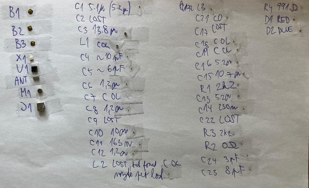
And I was able to reliably draw interconnection of parts on PCB. Here it is:
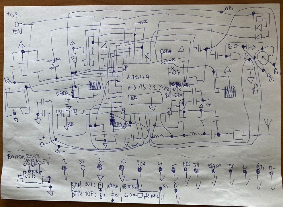
Okay, it looks strange. It matches physical layout on PCB but it is actually quite useless, so I redraw schematics in Kicad and relocated symbols for easier understanding. After reversing, some signal start make sense, so I named them. Here it is (click for zoom):
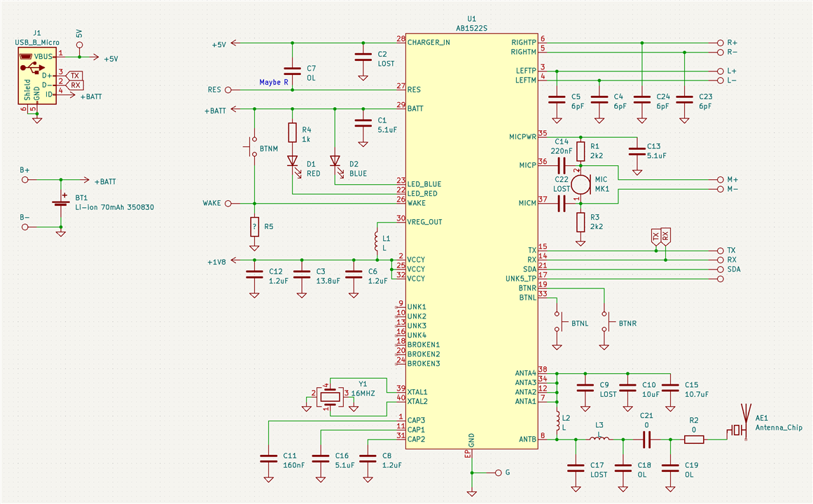
Some notes about connection
- Main chip is Airoha AB1522S. Documentation is not public, but I found at least basic information about chip which correspond to device parameters.
- Antenna connection looks standard, I do not have LCR meter, so values of parts are unknown. 0-ohm resistor is most probably for some testing or compliance checking. Many RF designs which I have seen includes it.
- Some pins ANT1,2,3,4 are most probably outputs of some internal regulator. C9, 10, and 15 are most probably decoupling caps for this regulator.
- Meaning of CAP1, 2, 3 is unknown since only capacitors are connected to it. Most probably they are some internal regulators.
- RX and TX pins are fancy. Note that they are connected to USB connector. Funnier thing is that they do not carry USB signal and even more, they do not carry UART also. Practical measurement with scope shows that the TX signal looks like some UART, but it is very high-seed and do not follow any standard UART parameters (character most probably is not 8-bit wide, start and stop bits are irregular, …). I also did not decode any character on it. Looks like some high-speed binary trace.
- Middle button is connected differently and it confused me when reversing first time. But now it make sense. It is pulled to battery and can act as some deep-sleep wake up for main chip (other buttons can’t wake it and it correspond with user-visible behaviour).
- LEDs are connected directly to battery which voltages vary, but as user I never realized varying brightness. Blue LED is even without any resistor.
That’s all for now. Thank you for reading it. If you have any comment, feel free to comment below and in next part I will try replacing battery by fake “very” sophisticated battery emulator and test if device work with it. This will allow me to remove need for charging device.
Next blog: Blog #3: Fake battery emulator