Intro
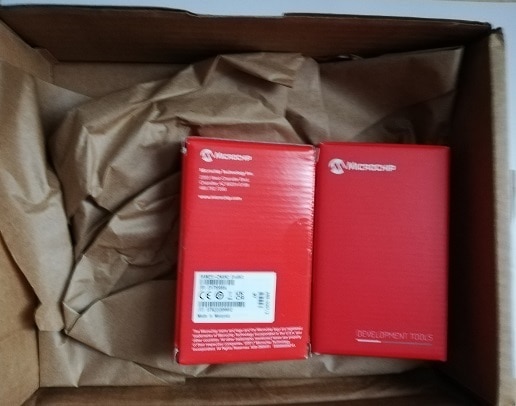
Every design challenge should have an unboxing blog, that is traditionally one of the first written. Unfortunately because of some delays and availability problems, I have just obtained most of my design kit, which I can now proceed to unbox. The package has arrived - as usual - well protected against accidental damage, with paper filling around the modules:

This time, two modules have arrived: Curiosity Nano module and the base board, with sensor boards still on the way.
In this place, I would like to thank both Microchip (challenge's sponsor) and the Element14 staff for providing us with components to build our projects in this challenge.
Base system
In this challenge, base/common part of the project was planned do be:
Main part, Curiosity Nano board hosts SAME51J20A MCU, equipped with powerful set of features, including:
- ARM Cortex-M4F running up to 120MHz,
- hardware FPU,
- DMA controller,
- one Four-LUTs Configurable Custom Logic,
- 1024kB of FLASH with ECC support,
- 256kB of RAM (128kB when ECC enabled),
- hardware encryption offload with wide range of algoritms,
- wide range of hardware serial interfaces, including I2C, I2S, SPI, LIN, RS485 and CAN,
- dual 12-bit ADC (this one is omitted in the overview page on the manufacturer's portal - bug report has been filled-in on the website),
- dual 12-bit DAC
- one Full-Speed (12Mb/s) USB interface supporting both host and device function
In addition to the MCU, board includes on-board debugger with programming, debugging and virtual com port (CDC) features and adjustable voltage regulator, capable of generating voltage in the 1.8-3.6V range.
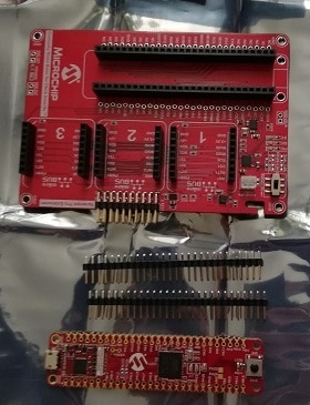
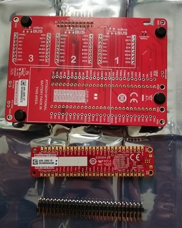
In addition to the processor board, baseboard (called Curiosity Nano Adapter) was also provided. This one provides:
- three sockets for mikroBUS modules,
- one e Xplained Pro Extension Header
- power supply for powering Curiosity Nano board and the modules with Li-Ion battery charger built-in
Both boards are of good quality, with detailed pin descriptions on the solder-mask and (in case of adapter board) rubber feet for stable placement on the flat surface.


mikroBUS Click modules
The sponsor generously offered to provide us with up to two mikroBUS modules of our choice - which, considering staggering number of different version available (currently 1565 models present on https://www.mikroe.com/click-boards website), was a very interesting possibility.
Considering that my project needs at least:
- possibility to measure mains voltage (to detect energy overproduction event),
- and receive data from wireless sensor installed inside a refrigerator (to avoid excessive temperature drop during energy storage phase),
I have started searching. After initial analysis of the possibilities it became evident that I cannot directly measure mains voltage - modules are designed for prototyping and are generally prepared to operate with safe voltage levels (even the ones that incorporate components like advanced mains power metering chips are built for low voltage).
In this situation I have decided to use RMS to DC module rated for voltage up to 5V AC, that is providing RMS to DC conversion paired with MCP3221 ADC, connected to the low voltage mains transformer.
To receive data from 433MHz wireless weather sensor working as temperature sensor inside the fridge I have decided to use OOK RX module, designed to receive OOK/AM modulation with the hope of porting existing receiver library to it.
Unfortunately, neither of those modules has arrived to this day, so some temporary alternative solution has to be prepared.
Summary
Considering that first part of the hardware arrived only recently and deadline looming, I am afraid I have to resort to prepare some temporary solution using different hardware, with the hope of porting it to the target architecture in the later time...

-

DAB
-
Cancel
-
Vote Up
0
Vote Down
-
-
Sign in to reply
-
More
-
Cancel
Comment-

DAB
-
Cancel
-
Vote Up
0
Vote Down
-
-
Sign in to reply
-
More
-
Cancel
Children