


Hi vertical farmers,
On our second post we present the hydroponic system prototype that we will be using during the course of this challenge. It has been a long and hard week, but worth it!
So, in our previous post we described the top level of the system architecture, enumerating all the modules of our vertical farm prototype. Today we will show not only a detailed scheme of the Hydroponic structure and sensors but also the actuators that control the water flow and the nutrient dosage.
The following figure illustrates the general idea of the system.
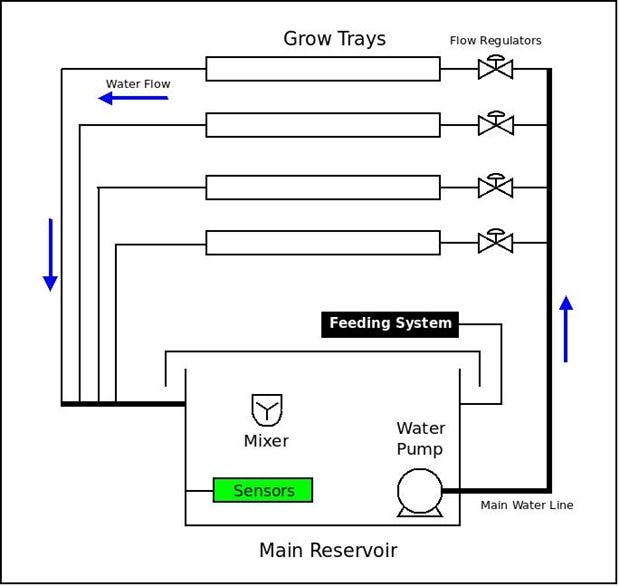
Here, a main reservoir holds a nutritive solution composed by several nutrients dispensed by an automatic feeding system. A mixer helps to homogenize and oxygenate the nutritive solution that is monitored by sensors placed in the reservoir in order to control its parameters. An electric pump is used circulate the nutritive solution in a closed, recirculating system.
And now comes the experimental setup. The built prototype is shown on the following image.
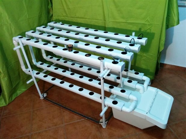
This setup can grow up to 80 plants that share the same nutritive solution that is stored on a 40 liters reservoir. The plants should be of the same species as different plants may have different nutrient requitements. The system is self contained and can be replicated for different plants. For instance we can grow leaf vegetables on one and strawberries (or other fruits) in another one and fine tune the nutritive solution for each plant.
The kit structure and pipes (grow trays) are made of PVC(Polyvinyl chloride). Those PVC pipes are safe for food production. They are black inside to avoid proliferation of algae or other microorganisms and the white skin is used to limit the temperature increase of the nutrient solution under direct sun exposure.
The pipes feature a small inclination that helps the nutrient solution to flow from the top level, to lower level and reservoir. The designed system is modular in the sense that more levels can be added vertically provided that the pump have sufficient capability to sustain the nutrient solution flow.
The Hydroponic technique used (NFT) doesn´t require a substrate. The roots can be placed directly on the nutritive solution. Nevertheless some baby plants may need some physical support to be hold on place and therefore we may test the use of expanded clay or other inert substrates on plastic pots.
The solution is pumped to the top floor via a recirculating pump submerged inside the reservoir. The pump is shown on the next image.
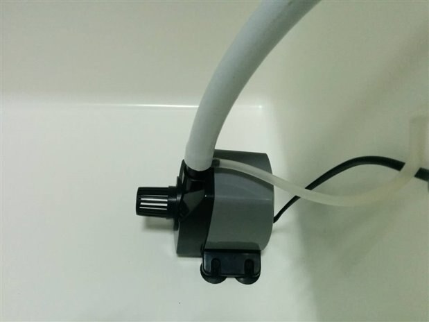
It can be seen it features an air intake that helps to oxygenate the nutrient solution. It´s a 22W pump with 1000L/h and 1.6m max. lift.
To equalize the nutrient solution flow on each of the four branches running in parallel a pressure compensating, constant flow dripper is used on each intake microtube according to the initial diagram.
The system will feature as well an automatic dispenser for 2 different nutrient concentrated solutions, water, and a pH regulator (mainly an acid to lower the pH) according to the following diagram:
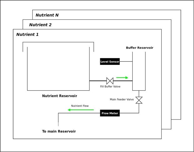
The dispensers use the same working principle. A Main reservoir holds the liquid and controlled electrovalves are used to transfer a certain amount of this liquid to a buffer reservoir. A level sensor is used to determine the volume of liquid that will be poured on the Nutritive solution reservoir. When the correct level is detected the fill buffer valve closes and the liquid is released passing through a flow meter that double checks it as a safeguard.
Once on the nutritive solution reservoir, the different components are mixed and oxygenated by an air pump to achieve an homogeneous solution. The reservoir is constantly monitored by an array of sensors ( pH, EC, temperature) in order to keep an optimum balance on the solution parameters.
On the next post we will further detail the choices undertaken to build the automatic nutrient dispenser and monitoring the parameters of the nutritive solution.
Feel free to put any questions or share your thoughts and suggestions on our design and methodologies.
Keep in touch!
Top Comments