


Over the last 2 weeks I have come to realize that I am running out of time to do everything I want, and I will have to simplify things a bit in order to get something useful done by the end of the competition. Unfortunately I have run into issues with both time and funding. I also realize I have slacked a bit on the blogs. This is not because I haven't been making progress, but because I have been focusing more on actually getting the work done than reporting about it. So, in this blog I will explain some of the design changes I have made in the interest of getting this project finished. I don't think I have sacrificed anything in terms of overall functionality, but the result is not going to be as pretty or as customized as I would have liked.
First off, I will be using breakout boards instead of creating a custom PCB for this project. I had originally planned on running everything off of the EZR32WG starter kit board with just one PCB with all of the I/O and power management. Instead I will be using an off the shelf 8 channel relay module for all of my outputs. I will be using a ACS712 module for measuring the current used, and I will be using a small breadboard for the interface with my other sensors. This will not be as clean as I would have liked, but it will work the same in the end.
The other major change is that I have decided to use an Arduino as the interface with the I/O and sensors, and have it communicate through UART with the EZR32WG instead of having the EZR32WG directly interacting with sensors and relays. This is purely to save time since I have working Arduino code for all of the parts of the project, I just need to bring it together in one program. The EZR32WG will handle all communications with the main server, keeping time, and polling the Arduino for data.
Here is a schematic of what is essentially the final hardware design. I have attached it as well for a clearer view.
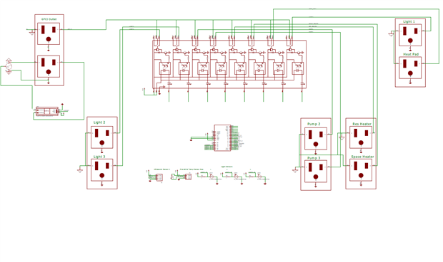
To summarize, there are eight relay outputs controlling 3 lights, 3 heaters, and 2 pumps. There are 4 temperature sensors, one water level sensor, 3 light sensors, and one current sensor. This solution will provide feedback for 6 of the outputs and measurement of total power used.
My next post will show the physical wiring I have done so far which is almost done. After this, I will complete the code for the Arduino and post it. Then I will code the EZR32WG communications, post that code, test the entire system and post the results. Then, if I had enough time I will finish the web based SCADA system I described in blog 5.
| Pump_Control.pdf |
