


For this week I have been preparing a post focusing a little bit on how all these wireless power devices work. It’s not my intention to explain the theory, it’s more like taking a closer look at some of the signals, try to reproduce some figures from the datasheets etc.
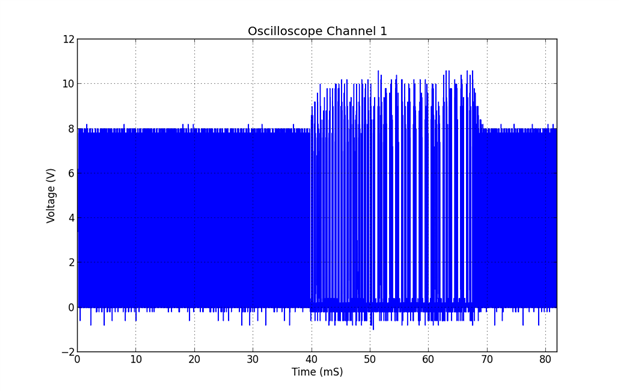
When we power up the transmitter (at first without a receiver), it starts emitting a digital ping every 500 ms. This ping is what we can see in figure 1.
<html><head><title>Jive SBS</title></head>
<body><font face="arial,helvetica,sans-serif">
<b>Error</b><br><font size="-1">
An general error occurred while processing your request.
</font></font></body></html>

If we zoom in we see that the individual waves forming the ping signal. Their frequency is around 178kHz.
In the next image we can see the startup procedure when a receiver has been placed on top (with no load). The wave frequency then dropped to around 125kHz.


Increasing the load from 0 to 500mA made the frequency increase to 147 kHz. From 500mA upwards till 1 A frequency decreased again, but the amplitude of the wave increased.


All of the previous scope images are captured at TP1 of the receiver board.
Let’s now take a look at the receiver board. I think probably the first think we want to measure is the Output voltage and the rectified voltage. After all, that’s what the IC is for! The following screenshot shows both Rect (TP12, Yellow) and Vout (TP7, Blue) on a 1ms/div timebase. We can clearly recognize the oscillations in the rectified voltage due to the amplitude modulation of the coils voltage for communication. The next one shows the response of the receiver to a load step of 300mA. As we can see, the output voltage remains stable despite the sudden increase of output current.
<html><head><title>Jive SBS</title></head>
<body><font face="arial,helvetica,sans-serif">
<b>Error</b><br><font size="-1">
An general error occurred while processing your request.
</font></font></body></html>

Lastly I wanted to further investigate the modulation of the AC coil. The datasheet states that the coil modulation is achieved with the COMM1 and COMM2 pins of the IC.
So I hooked up the probe to TP3 (COMM2) and got the following signal:
<html><head><title>Jive SBS</title></head>
<body><font face="arial,helvetica,sans-serif">
<b>Error</b><br><font size="-1">
An general error occurred while processing your request.
</font></font></body></html>
We can clearly identify a data packet being send. A one is encoded as two transitions in 500us, while a zero is encoded as only one transition in the same time. This is called a differential bi-phase encoding scheme. For more information on it please refer to the datasheet of the IC or the specification of the Wireless Power Consortium, Part 6: Communications Interface
In the above picture we can count 21 “1”. This is the preamble of the message. The first zero (approximately in the middle) is the start bit of the header. After it, we receive two ones, followed by 6 zeros. These are the header bits, encoded LSB first (Value: 0x03) The next two ones are parity and stop bits of the header. After the header the message content is received: 1 zero start bit, 8 zeros message bits, and finally again two ones (parity and stop). This means the message content is 0x00. After the end of the message we still expect a checksum byte to be received, which is outside the screen capture on the right.
The next image is just to show how the COMM signal modulates the AC Coils Voltage Amplitude
<html><head><title>Jive SBS</title></head>
<body><font face="arial,helvetica,sans-serif">
<b>Error</b><br><font size="-1">
An general error occurred while processing your request.
</font></font></body></html>
I remembered having read something about controlling the Rigol oscilloscopes with Python from the computer at hackaday. And, after decoding the first packet by hand, I thought this would make a perfect occasion for trying it out and learning Python on the way.
So I started to look for that post that then led me to the following interesting webpages:
- http://www.righto.com/2013/07/rigol-oscilloscope-hacks-with-python.html
- http://www.cibomahto.com/2010/04/controlling-a-rigol-oscilloscope-using-linux-and-python/
- http://www.rau-deaver.org/Mac-PyVISA.html
So I copy-pasted the code from the first link and run it. As usually, nothing worked at first. Being a Mac user sometimes can really suck. (Only sometimes!). But I also found the appropriate tutorial on how to get my scope interface working with PyVisa. Instructions for it on the third link. After getting my scopes data nicely plotted on my screen the real work began, setting it up to capture the data packets and then trying to decode them.
I’m really sure there must be some standard way of demodulating a signal like this, or at least a proper technique. But as I’m neither an electronics engineer nor a programmer, I just started trying different approaches.
<html><head><title>Jive SBS</title></head>
<body><font face="arial,helvetica,sans-serif">
<b>Error</b><br><font size="-1">
An general error occurred while processing your request.
</font></font></body></html>
Fact is that, at the end, I got my scripts to decode the packets without (too much) trouble. The image above shows the blue data points from the captured signal and my decoded data in green. Next thing was to set up the scope to capture sequences of data in order to see a “live” stream of packets.
This finally also worked, and I was able to see how the content of the message changed when I varied the load. Nevertheless I have always decoded the same 0x03 header, never a different one. Obviously I’m never going to get a message from the transmitter to the receiver, as I’m decoding the receiver’s signal modulator, but I expected to find other packets like identification or Signal Strength.
If someone has a Rigol scope (I own a DS1052E) and wants to try my scripts out I could certainly write a more detailed description on how to run them, how they work and so on. But I don’t want to bore all of you, so I’ll leave it out for now.
I also stumbled across a very interesting application note from Freescale Semiconductor ( http://cache.freescale.com/files/microcontrollers/doc/app_note/AN4701.pdf ). In it they describe a circuit to demodulate all of the communication packets transmitted between receiver and transmitter. If I find myself with more free time I may attempt to build it.
With this post I finish the first part of my project which has been a review and some testing of the evaluation modules. Next week I will start with the design of the receiver and the considerations that go into it.
-

DAB
-
Cancel
-
Vote Up
0
Vote Down
-
-
Sign in to reply
-
More
-
Cancel
Comment-

DAB
-
Cancel
-
Vote Up
0
Vote Down
-
-
Sign in to reply
-
More
-
Cancel
Children