


Time for another status update. Unfortunately the last few days can be summed as "it does not work" 
My plan for the last days was to populate one functional component after each other on the PCB, and verify that they work as intended. Sounds simple, but wasn't.
A balancer that stumbles
I started with the one of the balancer modules. Soldering went fine. I needed some hot-air for soldering the FET - since I designed the area around it as heat sink the PCB really draws some heat away (which means it will work well has heat sink)
When testing it it did not go into balancing mode at 4.1 V as intended, but started doing so at about 1.9 V. Strange thing... Attaching the iMSO104 scope revealed that the reference voltage was oscillating really heavy. Looking at the data sheet for the LT6656 revealed that it needs at least 2.2µF output capacitance to be stable. Doh!
OK, so I added that cap (fortunately there were some pads available which made it fit nicely), just to see that now the OpAmp oscillates when going into regulation. Doh again!
Time to take another look into the data sheets - something I really should have done before... Turns out that the LT6003 needs a RC-series-combination (2.2k and 1µF) at its output to be stable with small loads. Why did I miss that in the beginning? There is a whole section in the data sheet about that...
After adding that the balancing mode was stable- until the shunt current exceeded 100mA. Then it went into oscillation again. Time to bite into the table plate
I tried to add a capacitor in various places to dampen the oscillation, but none of it helped. I even replicated the circuit on a breadboard (something I also should have done before), but found no real solution. But at least it worked up to 100mA, and I might live with that.
Some voltage conversion
So I went ahead with the DC-DC-converter. At least that one went fine, I got a nice 12.2V out of it, and was able to trim it to 12.4V. Since the balancing was unstable above 100mA, I changed the current sense resistor so the charge current is limited to 90mA (using two instead of one 0.5 Ohm resistor with a short wire in between). The current limiting also works nicely as it should. At least one good news.
Fast vs. slow signals
Next step was adding all the glue logic used for end-of-charge-handling. This area was rather crowded, so soldering was tricky. After managing that, when turning the circuit on again, I expected a power-on delay of about one second. But instead, I got - nothing. Now it got tricky. Sometimes it worked, sometimes not. So I attached the scope and the logic probes (fortunately the iMSO104 has both) to see whats happening. Turned out the reset circuit I designed won't work properly if the rise time of the supply voltage is too long. In that case, the reset signal would go to one even before the DFF starts working properly.
So I needed a much larger delay here. I measured the rise time for the wireless power receiver at about 1 ms. This is actually quite fast, but still to slow my idea to work. Since the set/reset signals don't accept slow-changing signals (the reason why I used such a short delay in the beginning), I added another AHC1G08 AND gate to handle that delay (the AHC series comes with schmitt-trigger inputs). Adding that one was tricky, and required serious dead-bugging. But after that, it worked as expected, without any hiccups.
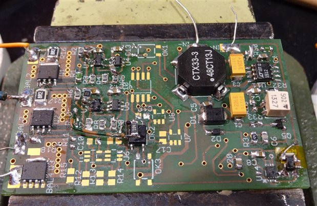
(I count 4 bodges in this picture, and there will be some more...)
LEDs and output current
On the next day, it got time to work on the rest of the end-of-charge detection. After soldering the opto-coupler, I (again) discovered that I should have tested this before. Though the OpAmp is able to drive the LED so the OC is active, this drops the output voltage enough so the FET will not shunt away enough current. Another look in the data sheet reveals that the rail-to-rail characteristics are only specified for an output current of 250µA, which is quite low. So it got time for another rework. I added a small NPN transistor to drive the LED, so the current drawn from the OpAmp should be low enough. What I also discovered then is that the LED in the opto coupler will also work as balancer. The NPN transistor will turn much earlier than the FET, so the LED will conduct current even before the FET will do so.
Working on that balancer
While I was at it, I populated one of the other balancer blocks. But this time I used the TLV2401 OpAmp instead. Its data sheet did not mention any special requirements for stability, so it seemed worth a try. This is one of the OpAmps I originally considered for the circuit, so I had some samples from TI laying in my parts bin.
I discovered that it would also oscillate without any precautions, but was stable of the full currency range with the additional 2.2k-1µF RC-series-combination. So I will change over to the TLV2401 instead of the LT6003. Even though its specs are little bit worse, the increased stability is important to me. So thats another good news. Unfortunately I had only two of them available, so I placed another order with TI, and it should arrive just in time. Thanks to TI for that!
The next day I re-tested the balancer, and verified that driving the opto coupler with a NPN transistor does not affect the stability. So that part of the circuit is fine.
Some lockout problems
Today I soldered the battery-switch for the under-voltage-lockout. This also worked as intended. Next step was the differential amplifiers for level-shifting the battery voltage to proper ground level. Soldering was quite OK (since I accidentally used a SO8 footprint instead of the intended MSOP the pitch was large, fortunately I ordered the TLV2402 in both packages...). But when measuring the voltage they were way of.
After much head-scratching I fired up LTSpice again, draw my circuit and found that it just won't come up with a stable solution. After some more head-scratching it was time for a face-palm: I completely messed up the differential amplifier circuit. I swapped both positive and negative OpAmp inputs, as well as the battery inputs.

Fixing that will require some serious reworking, I will need to think about how to do that. So this will be the task for tomorrow, together with adding the voltage comparators (and hopefully there won't be any more nasty surprises...). This then gives Thursday to mount everything into the snow groomer to finish up the project just in time. Oh, and I need to write at least one additional blog post...
At least I learned something...
So whats the result of that story? Its something I actually knew before: never make assumptions. If you do, verify them. Oh, and RTFDS - there is always important information in it...
It was a good idea to order for nearly all part more than just the ones I needed. That gave me some flexibility in reworking.
Ordering the PCB with Würth was also a good move in the aftermath. Their fast delivery gave me (hopefully) enough time to discover and correct all my mistakes. The the NiAu finish I did use is also more resistant to re-heating, which allow multiple rework passes without destroying the pads on the PCB.
-

mcb1
-
Cancel
-
Vote Up
0
Vote Down
-
-
Sign in to reply
-
More
-
Cancel
-

hlipka
in reply to mcb1
-
Cancel
-
Vote Up
0
Vote Down
-
-
Sign in to reply
-
More
-
Cancel
-

mcb1
in reply to hlipka
-
Cancel
-
Vote Up
0
Vote Down
-
-
Sign in to reply
-
More
-
Cancel
-

hlipka
in reply to mcb1
-
Cancel
-
Vote Up
0
Vote Down
-
-
Sign in to reply
-
More
-
Cancel
-

mcb1
in reply to hlipka
-
Cancel
-
Vote Up
0
Vote Down
-
-
Sign in to reply
-
More
-
Cancel
Comment-

mcb1
in reply to hlipka
-
Cancel
-
Vote Up
0
Vote Down
-
-
Sign in to reply
-
More
-
Cancel
Children