


Greetings fellow Earthlings!
In this living blog post, I will be documenting the build of my project for Build Inside the Box. See the section headers for the updates as they come. I'm planning to leave any previously-posted stuff alone; otherwise make notes as to what changed and why.
I won't be revealing the final project until I have it in working order, but feel free to guess down below 
The ingredients!
For this project, we were given a 'random' assortment of components and have to build something that makes use of all of them.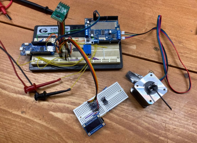
The Arduino MKR Zero is the main microcontroller for the project. This 32-bit SAMD21 should be pretty well capable of anything we can throw at it.
Other components:
- MulticompPro 10,000 mAh portable battery
- WAGO lever nuts
- MCP604 quad Op-Amp
- Photo interrupter
- OLED display
- Temperature sensor
- VL53L0X distance sensor
Link to project page here has all the official specs
To finish the competition, I must use all of the components.
Updates:
- 4/24/2021 - Initial Update
- 4/26/2021 - Analog circuitry for mic input
- 5/2/2021 - All working on breadboard and some mechanical components
Blog update 4/24/2021
Getting Started
The first task is to see if I can at least get all of the components talking to each other on a breadboard. I have a nice project in mind, and if I have time at the end, I'd like to make a PCB for this and have a more permanent 'display'.

Distance Sensors
I started by using the distance sensor - ST calls it the 530-SATEL-I1, but this is essentially just a breakout board for the VL53L0X distance sensor. The kit actually is a 2-pack. I had only planned on one, but have a clever idea on how to use the second one This uses a 2x5 pin header which isn't breadboard compatible, so I have it 'floating' above the breadboard on pin headers. Setting this up was relatively straight-forward and it ran using some sample code for the VL53L0X from Adafruit.
I was able to get readings and print them out to the serial port, then move my hand up and down in front of it and watch the values change. I did note that with distances <30mm then they all just read about 30mm. And values that are out of range, I just updated the code to read '-1' as the distance.
My project will use this sensor as one of the two main 'inputs' to the control algorithm.
Temperature Sensor
The kit comes with a Microchip MCP9701 temperature sensor. This reads the temperature and produces a linear analog voltage that corresponds. This is read easily with an analog input pin on the MKR. I read the data sheet to understand how this was set up. According to the sheet, this reads temperatures from 0°C to 70°C
To read this, I start with a simple analogRead(A4) to get the raw 10-bit value. with 0-70°C represented in 10 bits, that works out to 0.00322265625 V / level.
According to the data sheet, 400mv represents 0°C, so all calculations need to be offset by this. On the 10-bit ADC reading from 0-1024, that would be 124 'levels' that I need to first back-out of the calculation. So I take analogRead(A4) * 0.00322265625 to get the true voltage level, then I subtract 0.4V for my Zero offset.
The last step is converting the voltage value into a temperature. This was again based on the data sheet telling me that the MCP9701 uses 19.5V / Deg C. So I take the calculation from above and multiply by 19.5; (or rather 0.0195 since I'm reading milivolts instead of volts).
The final calculation is then:
float temp=((analogRead(A4) * 0.00322265625)- 0.4) /0.0195;
This gives me a pretty reasonable measurement although since I live in 'Merica it is a little hard to validate the metric version
Vishay Phototransistor / Photointerrupter
This component is pretty fun. At first, I wasn't entirely sure how I would integrate it, but I think I have a great plan on how to use at this stage. (I won't reveal exactly how until later though). This component is actually two-in-one. We have an LED that gets powered from 'something' - could be a micro, or could be just straight rail voltage. And the other side is a phototransistor which reacts (turns on) based on the amount of light reaching it.
This device is essentially the same as the 'business end' of an encoder. If I had two, I could create a proper quadrature encoder. I found in testing that the output only goes from 0.03 up to about 2.8 volts DC when an object is placed inside it. To rectify this into a proper 0-3.3V signal for the MKR, I used one of the channels on the op-amp as a comparator and got a clean on/off signal at 0/3.3V.

Microchip MCP604 Quad Op-Amp
This was another component that I wasn't sure at first how to use. This is a quad-op-amp in a DIP14 package. I had a general idea of the project I was building, but just not sure how this would be (or could be) used. Once I got into the project, I had a few good ideas, and think this will be a fun addition. The first use was using one channel as a comparator for the phototransistor, to ensure that I could use it on a digital pin and be confident that the microcontroller would be able to discern the on/off voltages correctly.
For the second use, I will be planning on a 1- or 2-stage amplifier for a microphone circuit. Again, not telling you what I'm doing with it just yet but this will be to create a binary on/off signal to the micro.
MIDAS OLED Display
This screen is a 128 x 32 pixel OLED display. Displays are pretty easy to use in many projects for a simple readout of setpoints and sensor readings. I'm planning the same with mine.
I unfortunately had a lot of issues getting this up and running due to the way it has been documented. There was a lot of confusion on my side as to whether this uses SPI, I2C, or some other protocol. The Adafruit guide for the SSD1306 [this is the chipset that is behind the display] notes "only uses SPI" but they go on to provide sample sketches for I2C and SPI. I probably would have preferred using I2C since I've already got a few components like the distance sensor on the I2C bus; but alas, I couldn't get it to show up or work on the I2C bus.
I posted on the main 'Build Inside the Box' forum and someone else noted that it uses SPI. I reluctantly tried this and was able to make it work. Again, however, the documentation was very poor. I2C uses pin names like SDA and SCL; which the board had right there. SPI uses pins like MISO, MOSI, SS where were completely absent on the board. The Adafruit tutorial doesn't give a proper schematic either, it just says what the image below shows; which doesn't adequately describe te pins. This was also written (I believe) for an Uno which has a completely different chipset than the MKR Zero; so I couldn't trust the instructions.
So after a lot of messing around; and some re-pinning of the connections, I was able to run the sample code for the 128 x 32 OLED screen
Thanks to kmikemookicking me in the right direction to get the screen running


Wago Lever Nuts
I'll be using the Wago lever nuts to connect some wires. I actually really love these connectors and have carried them in my backpack for years. They are super useful and easy to use, and even are UL / CE approved. The kit comes with some DIN rail attachments and backplane attachments for the lever nuts,; but i'm not sure those specific parts will be in the final build.
Power Supply
The Multicomp Pro power back is pretty awesome. It is rated at 10,000 mAh for USB B. I recently got a DC load and was able to test this battery to see how it performs. It is rated at 2 Amps, and I was able to run a complete test with a 1-Amp load. It was able to output about 7200 mAh which wasn't too shabby. I was a little disappointed that the voltage was only about 4.3V average, though.


I got a lot of noise in the readings where the different measurements would come in as zero. Not sure what that was about. But at least we can follow the general trends in the chart. For my project, I'm using a stepper motor and it sucks a lot of juice - ~1.3 amps nominal with the stepper enabled. Not sure I'll be able to power the stepper from this or will need an external supply. I do have some large bulk caps that I'll try to use though.
Other Components
Above I have listed all the required components of this competition. In addition, I am using a stepper motor and a few other minor components. Part of that is three 10-turn trimmer pots for dialing in some control algorithm settings. The stepper is run through an Adafruit Stepper shield and using a 200- step/rev motor.
Next Steps
The next things for this project are as follows:
- Get all running under one sketch.
- I'm actually most the way there on this. The screen problems threw me for a loop, but I've got that figured out
- Currently, I have three analog pins reading the 10-turn pots, another pin reading the temperature sensor, and the I2C bus talking to both the stepper driver and the distance sensor all in a single sketch.
- I've got sketches to control the stepper based on either the temperature sensor reading, analog pin reading, or the distance sensor reading.
- Have to integrate the screen, and op-amp inputs (microphone and photo-interrupter) next.
- Mechanical build
- Have to create a stand and mechanical parts to make the project actually work all-together.
- Not revealing until later what I'm building; but feel free to guess down below

- Final coding and programming
- Once mechanical build is complete, I can do the proper coding to make this do what I'm wanting
- PCB?
- Only if I have time... otherwise this will be a breadboard affair.
Thanks!
Updated
Blog Update 4/26/2021
Analog circuitry
Microphone to digital input
In this quick update, I'll post progress on the use of the op-amp. I realize that this was /actually/ my next step after the post up above. I really needed to get this finalized so I felt comfortable going on to the next step. I have a microphone that I need to use to detect a loud sound. To do this, I really wanted to use a digital input pin on the micro. I'm not trying to do any fancy voice detection or anything like that, just let me know if there is something loud. I knew that with the Op-Amp, I could both amplify the microphone's output signal up into the "volts" range (like ~1 to 3 V), and also convert it into a digital signal.
The design I worked out uses three stages of the op-amp. The first stage is a basic microphone pre-amp. The output of this is fed into the second stage as an analog signal. The trigger (inverting) voltage on the second stage is set at about 1V, and on the output I've used an R/C circuit to stretch the signal. The analog waveform that I was capturing was around 1-2 ms, and if read straight into a microcontroller could trigger the input multiple times for each 'sound' that I capture (again; not revealing what I'm building until I get farther along... ). So I'm using the R/C circuit to both debounce and stretch.
I then feed this into the third stage which serves like a comparator (same as second stage) but really to clean up the edges. The R/C circuit output signal is a sharp rising edge followed by a long decay. So using the last stage I can select the cutoff voltage within that decay (as my non-inverting input) and have a nice clean digital on/off signal come out the other side which is now about 65 ms long and much easier (trivial) to read on a digital pin.
This is /by far/ the most analog circuitry I've really ever done, and first time not following a boilerplate example. I basically took the building blocks I knew and starting stringing them together. I knew that I could use the op-amp to amplify a microphone. I knew that I could use an R/C circuit to make a time-constant. I knew how a comparator worked. Just had to smush them all into one complete circuit. Initially I struggled with the R/C portion of the middle since I wasn't getting the delays I wanted. There were a few different ways of doing this with different components (like a common transistor) but I really wanted to use the op-amp. I finally realized looking at my schematic and also this post from EE Stack Exchange that I could use a diode to feed the R/C circuit. It took a while since they are doing different things in that circuit than I am and I had to sort out what each part was doing. By adding that in-between stages, it lets the voltage at the top of the RC circuit come up essentially immediately to the right level, then fall according to the logarithmic time constant. I think what happens without this diode is that the voltage back-feeds through the op-amp to ground, and it cancels out the bleeder resistor. (someone please correct me if I'm wrong on that assumption). Either way; the instant I added this, I got a beautiful clean R/C decay with 'instant on'. This fed into my last stage and I now have a clean digital signal for the microcontroller.
Photo interrupter
I know this was mentioned above, but I also am putting it here since I have a complete circuit digram to share. I'm debating making a board for this, but have to find or create basically all components into my Fusion (eagle) library and not sure I'll have time to do that, create the board, and get it here and assembled before the deadline.
As noted above, this gives a voltage swing from 0 to about 2.7-2.8 volts. To ensure this is cleanly read by the Arduino MKR, I used one section of the op-amp as a comparator. This also means that I've neatly used all four sections of the op-amp . The data sheets notes to not let pins float if unused, but I don't have to worry about that now.
| {gallery} Analog Circuits |
|---|
A mess of wires: Scoping the various stages in the microphone circuit. |
Analog Schematic: schematic of the analog signal processing and conditioning. |
Clean digital output: This is the three stages of the circuit. Top trace is the raw analog; middle trace is the RC decay, third stage is the clean digital sigal with the pulse stretched out. |
Mistake circuit layout: This is the trace I kept getting when trying to work on the R/C circuit without the diode. I was getting digital signals out the end, but without having the diode, I got no benefit from the R/C circuit and the signal was very noisy. Would have been a pain to debounce in software. |
Don's Sneeze!: Had to be super careful working around this mess! A few times, I'd hook the probes on the wrong wire and wonder what I had done to ruin the design... |


That's it for this post. Let me know if you have any questions or how I could have done this better. I stopped short of just looking up a "The Clapper" circuit since I wanted to figure it out myself a little bit. This way I've learned more about R/C circuits and how op-amps work.
-James
Blog Update 5/2/2021
Today's update is about some of the mechanical components being finished up and the fact that I've got all the components working on a breadboard together.
I've got the mechanical parts about 90% done. I did a couple rounds of 3D printing and think I'm happy with the results. I'll show the pieces here /not/ in their final form since I'm still not revealing what exactly I'm building (but feel free to guess down below!)

I was able to push the battery pack up to 2.5 amps and it will run for 'a little while' before shutting down. This will make using the motor easier for my build

I also have all the parts working on a bread board and reporting to the OLED display. Here is a quick video of the results -
Next updates???
Use an interrupt for the microphone input to ensure capturing it every time.
Finalize mechanical build so that I can do the 'real' coding.... Updated
Top Comments