element14 Community
element14 Community
    Register Log In
  • Site
  • Search
  • Log In Register
  • Community Hub
    Community Hub
    • What's New on element14
    • Feedback and Support
    • Benefits of Membership
    • Personal Blogs
    • Members Area
    • Achievement Levels
  • Learn
    Learn
    • Ask an Expert
    • eBooks
    • element14 presents
    • Learning Center
    • Tech Spotlight
    • STEM Academy
    • Webinars, Training and Events
    • Learning Groups
  • Technologies
    Technologies
    • 3D Printing
    • FPGA
    • Industrial Automation
    • Internet of Things
    • Power & Energy
    • Sensors
    • Technology Groups
  • Challenges & Projects
    Challenges & Projects
    • Design Challenges
    • element14 presents Projects
    • Project14
    • Arduino Projects
    • Raspberry Pi Projects
    • Project Groups
  • Products
    Products
    • Arduino
    • Avnet & Tria Boards Community
    • Dev Tools
    • Manufacturers
    • Multicomp Pro
    • Product Groups
    • Raspberry Pi
    • RoadTests & Reviews
  • About Us
    About the element14 Community
  • Store
    Store
    • Visit Your Store
    • Choose another store...
      • Europe
      •  Austria (German)
      •  Belgium (Dutch, French)
      •  Bulgaria (Bulgarian)
      •  Czech Republic (Czech)
      •  Denmark (Danish)
      •  Estonia (Estonian)
      •  Finland (Finnish)
      •  France (French)
      •  Germany (German)
      •  Hungary (Hungarian)
      •  Ireland
      •  Israel
      •  Italy (Italian)
      •  Latvia (Latvian)
      •  
      •  Lithuania (Lithuanian)
      •  Netherlands (Dutch)
      •  Norway (Norwegian)
      •  Poland (Polish)
      •  Portugal (Portuguese)
      •  Romania (Romanian)
      •  Russia (Russian)
      •  Slovakia (Slovak)
      •  Slovenia (Slovenian)
      •  Spain (Spanish)
      •  Sweden (Swedish)
      •  Switzerland(German, French)
      •  Turkey (Turkish)
      •  United Kingdom
      • Asia Pacific
      •  Australia
      •  China
      •  Hong Kong
      •  India
      •  Japan
      •  Korea (Korean)
      •  Malaysia
      •  New Zealand
      •  Philippines
      •  Singapore
      •  Taiwan
      •  Thailand (Thai)
      •  Vietnam
      • Americas
      •  Brazil (Portuguese)
      •  Canada
      •  Mexico (Spanish)
      •  United States
      Can't find the country/region you're looking for? Visit our export site or find a local distributor.
  • Translate
  • Profile
  • Settings
element14 presents
  • Challenges & Projects
  • More
element14 presents
e14 presents blogs Small circuits - Ideas needed for my Fidget Cube!
  • Blog
  • Forum
  • Documents
  • Polls
  • Files
  • Members
  • Mentions
  • Sub-Groups
  • Tags
  • More
  • Cancel
  • New
Join element14 presents to participate - click to join for free!
  • Share
  • More
  • Cancel
Group Actions
  • Group RSS
  • More
  • Cancel
Engagement
  • Author Author: hifromkatie
  • Date Created: 25 Oct 2021 3:19 PM Date Created
  • Views 5534 views
  • Likes 4 likes
  • Comments 26 comments
  • tinypcb
  • Cube
  • element14 presents
  • fidget toy
Related
Recommended

Small circuits - Ideas needed for my Fidget Cube!

hifromkatie
hifromkatie
25 Oct 2021

Hi all!
I'm currently working on an element14 presents project, to make a electronics/engineers fidget cube. What do you think, good idea?

My original aim was to make a 1" cube with small circuits on each side, but fairly quickly I realised this was going to be tight on space, I have now upped the size to 50mm cube (approx 2").


My design spec is as follows:

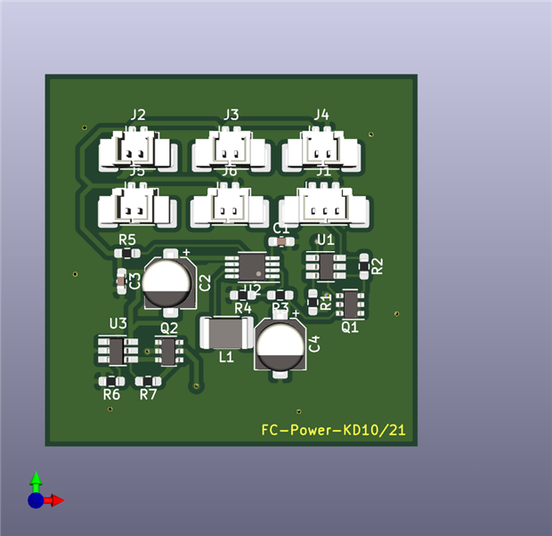
  • One side is a power supply, has a LiPo battery input and outputs 5v to 5 Molex PicoBlade connectors.
    • Pin1: +5V
    • Pin2: GND
  • Each side is completely stand-alone, has no dependency on any other side, other than the power connector.
    • All processing must be done on that side's PCB
  • The visible area of each side is 40mmx40mm
  • The PCB is 44mm by 40mm (This has a 2mm edge on 2 sides to slot into a 3D printed framework which will hold all the PCBs in to a cube shape.


I currently have the Power supply PCB designed, this also includes a fidget element of a push button which will turn 8 LEDs on and off

Front and Back:

imageimage


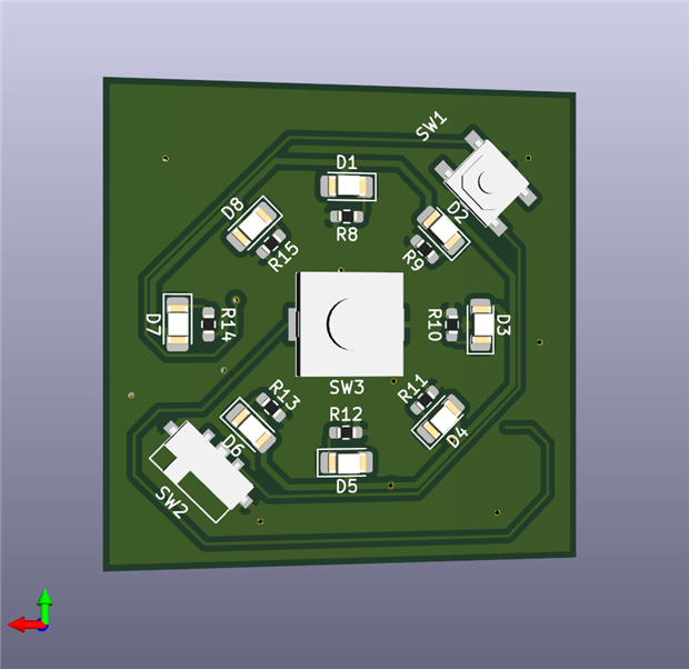
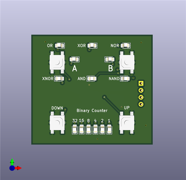
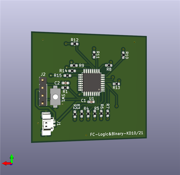
The next side I have designed is a logic gates and Binary counter board.
The top half has inputs A and B, and surrounding them the output of the following gates, based on input A and B, OR, XOR, NOR, XNOR, AND & NAND.

The lower half has a 6 bit binary counter, with a button to increase and decrease the counter.


Front and Back:

imageimage


I am planning on a "sketch side" which will consist of an LCD or OLED display and a joystick which will allow you to draw lines on the screen (Think Etch-a-Sketch).

This is currently proving hard to fit into the space and design requirements, but I think I've got a solution, but I haven't modelled this yet, so you might just have to trust me on this one (and I'm desperately hoping I've done the PCB correctly for it to all work like I've planned!)


The framework to hold these into a cube will be 3D printed, and currently looks like this:

The red is the top half and the blue shows the bottom, these will slide over the PCBs due to a groove on the 4 outside faces. The top and the bottom will need some hotmelt glue or other fixing method designed into the 3D print to hold them in place. Potentially an internal framework which will push against the back of the PCB and also securely hold the LiPo battery pack.

image


So what do you think of this idea?
Have you got any suggestions for the sides I've already come up with? Improvements, or criticism welcome!

I still need 3 sides, if you have an idea for a side then please let me know and I can design it for the cube. Or if you would like to try designing a side I'd love to see your design.


With the sides being independent and fitting the design criteria, I'm thinking they could be interchangeable and swapped in and out.
We could invent our own swapping system, if someone designed a side and makes a few and swaps them with other people who've made their own, we could all make our own unique fidget cubes!

Please feel free to tell me if I'm getting carried away now...!

  • Sign in to reply
  • thewildotter
    thewildotter over 4 years ago in reply to hifromkatie

    A Modest Proposal for a Fat-Finger-Friendly HMI

    Ah!  Neopixels.  So, make an  array by putting a bunch of neopixels beside each other.  Put a touch vector along each side of the neopixel rectangle.  A touch vector is a bunch of "momentary contact"  switch points along the edge of a rectangle.   In software, take the max and min of closed switches from your touch vector and highlight the line of LEDs in the middle of that range.  To highlight use 1/8 second video/reverseVideo cycling.  You should see a flashing line extending from the middle of your fingertip across the neopixel "screen."  When you have selected the line you want, touch a separate "OK" switch point with some other finger.  Do the same thing for both x and y of your neopixel "screen".   Use a "query selection" separate switch to video cycle the pixel you believe you have selected.  If it is correct, confirm it by touching OK.   The selected pixel should be remembered until you repeat the process to select a different pixel.   The touch vector edges of your neopixel "screen" can be repurposed now to select the coarse brightness value for each of the contributing colors R, G, and B.    I would use the corner pixels of your screen to display the brightness  of each color plus the fourth corner can be used to display the actual composite color.   Tapping the RGorB corner switch(es) can select which color you are currently adjusting for brightness.  Tapping the RG&Bcomposite corner indicates that you are selecting the magnitude of the adjustment range(coarse,fine, finer?) you are applying with your vector finger.  A vector finger should be placed approximately where you estimate you want it and then you can roll/press it to adjust by looking at the reverse video line it projects across the array.   In general, you can use any edge of your "display" as your current touch vector input.  The software should just pay attention to one edge at a time by virtue of noticing which one seems to be changing.  This allows  a user to put the finger where it makes the most sense,  is the most comfortable, and disrupts the view the least.  This whole discussion is just a "straw-man" to give you a possible human interface process for pixel selection and color value setting for editing your display (in any pixel order) or perhaps initially constructing your display data.  It avoids some of the "fat finger" dilemmas some designers experience when inventing a tiny touchpad user interface.   The exact chosen details, of course, are totally up to you and your users.

    ____________

    thewildotter

    • Cancel
    • Vote Up 0 Vote Down
    • Sign in to reply
    • More
    • Cancel
  • hifromkatie
    hifromkatie over 4 years ago in reply to Jan Cumps

    I like the idea of touch buttons/switches, and would reduce the amount of space taken up by physical buttons.
    Jan Cumps Interesting idea about changing the intensity of an LED, has made me think about the large box of neopixels I've got, maybe I could change RGB using 3 touch pads.

    • Cancel
    • Vote Up 0 Vote Down
    • Sign in to reply
    • More
    • Cancel
  • hifromkatie
    hifromkatie over 4 years ago in reply to beacon_dave

    Dave, When I first started the project I did start out that the side would only be active if at the top, but took it out again for simplification and reducing components/costs. It would be something to revisit, especially if any of the sides were noisy etc

    • Cancel
    • Vote Up 0 Vote Down
    • Sign in to reply
    • More
    • Cancel
  • hifromkatie
    hifromkatie over 4 years ago in reply to cstanton

    My original design decided that no board would ever interact with another board, just to make it easy to swap out sides.

    The idea of a clear cube, and things to see inside is a nice idea though, I like that too.

    • Cancel
    • Vote Up 0 Vote Down
    • Sign in to reply
    • More
    • Cancel
  • hifromkatie
    hifromkatie over 4 years ago in reply to cstanton

    Thanks another great idea, using a motor hadn't crossed my mind at all. I'm sure I've got a small off balanced vibration motor here somewhere

    • Cancel
    • Vote Up 0 Vote Down
    • Sign in to reply
    • More
    • Cancel
<>
element14 Community

element14 is the first online community specifically for engineers. Connect with your peers and get expert answers to your questions.

  • Members
  • Learn
  • Technologies
  • Challenges & Projects
  • Products
  • Store
  • About Us
  • Feedback & Support
  • FAQs
  • Terms of Use
  • Privacy Policy
  • Legal and Copyright Notices
  • Sitemap
  • Cookies

An Avnet Company © 2026 Premier Farnell Limited. All Rights Reserved.

Premier Farnell Ltd, registered in England and Wales (no 00876412), registered office: Farnell House, Forge Lane, Leeds LS12 2NE.

ICP 备案号 10220084.

Follow element14

  • X
  • Facebook
  • linkedin
  • YouTube