


Hi all,
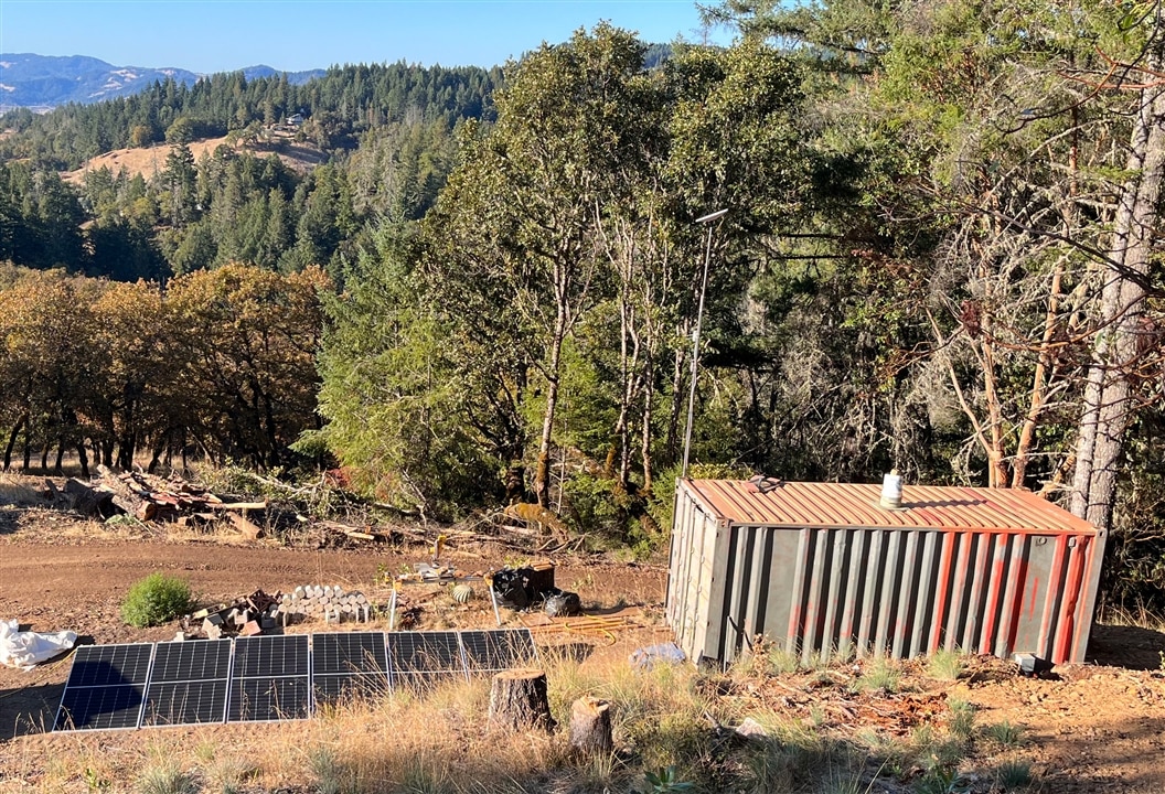
Good news, power is up!

In the last update, I had PAW (Power And Water container) ready, the trench dug, and the termination done at both the backer-board and inside of PAW. All that was really left to do was hook it all up. Maybe...
If you want to see detailed specs for the system, they can be found in this blog post.
To summarize, I am installing:
- Two Victron quattro 10000w inverter/chargers in a split-phase system. 20Kw total.
- The Victron 1000A Bus system, includes the Lynx Distributor (Fusing and monitoring), the Lynx Shunt (Main system fuse and monitoring), and the Lynx Power in (Battery connections).
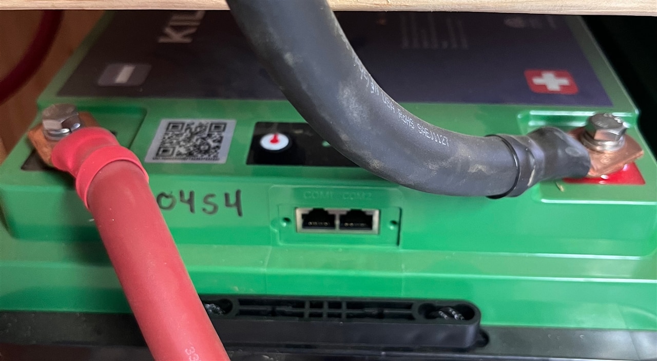
- Eight Kilovault 12v 300Ah LiFePo4 batteries in a series-parallel configuration for 48v, 600Ah. Total of 28,000Wh.
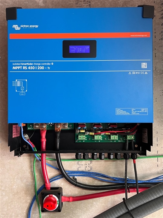
- Victron MPPT RS Charge controller, 450v, 200A for the solar panels.
Preparing the Wall of Power
The room I built inside of PAW is all plywood, and I want to be extra fire-safe. I put hardie-backer concrete board on the wall where all of the equipment will be mounted. You will see this in the following pictures.
Inverter/Chargers
These things are huge and very heavy. I have not opened the main compartment, but I am guessing there is a monster transformer inside. I had to call a friend to come help me mount these on the wall. They have a bracket that gets mounted to the wall first, and I used six 50lb toggle bolts for each. More than enough for the 128lb (58kg) of the inverter. They went up pretty easy with two people, and very exciting to see the first gear mounted on the wall!
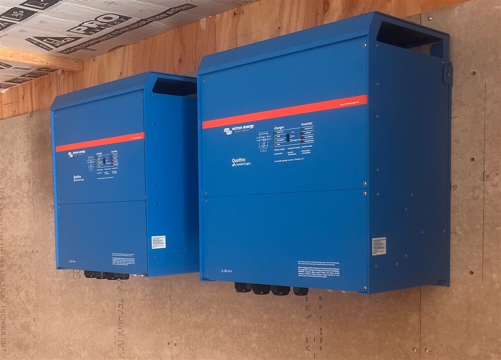
From everything I have learned about split-phase systems, It is important to make sure that the cables coming from the battery to the inverters are the same length and size. I mounted them close together - with appropriate spacing between - so the cables could be as short as possible, and because it looked good. 
Charge Controller
The charge controller also had a mounting bracket which made it very simple to install with just a few screws. The connections are pretty simple on this device, it has four MPPT trackers with their own connections and an output to the DC bus. I installed a cut-off switch inline on the DC output so that I can completely lock-out any power coming into the system from solar panels when I am working on it. It also has a CANBUS connection that connects to the Victron CANBUS for data collection. The fusing for this device is in the Lynx Bus.
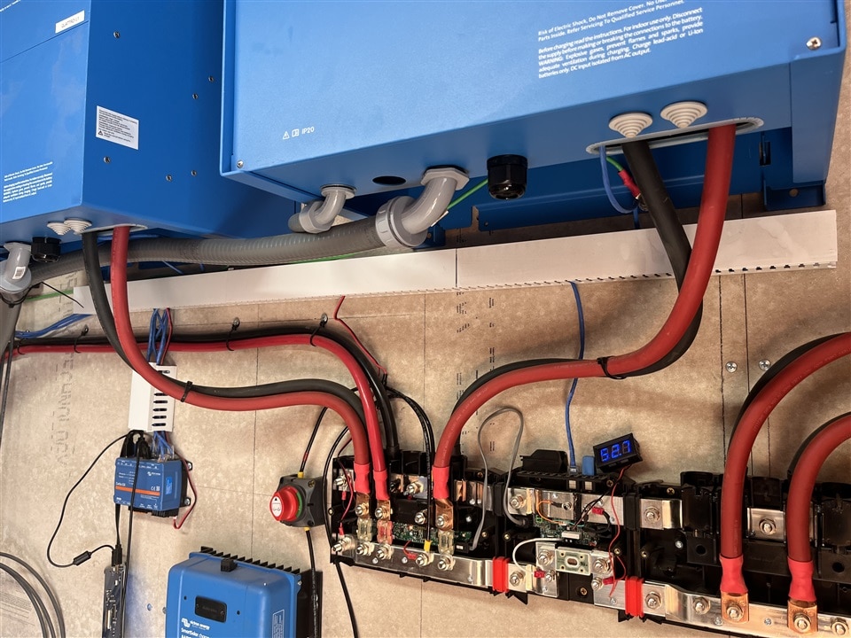
Lynx Bus
The next part to install was the Lynx bus. I carefully mapped out the placement of the lynx devices based on the location of the inverters to keep those cable lengths short and the same length. Each component is very light and easy to install with regular screws. They all bolt together creating a single unit with the 1000A bus. The Lynx Distributor (Left) has four connection points, each with its own fuse. I used the two outside connection points for the inverters, and the inside left for the charge controller. The Lynx Shunt (Center) does not have any connections, it's just the shunt with data output via CANBUS, and the Distributor connects to that with an RJ11 cable. The shunt reports information on the DC bus, voltage, State of Charge, Current, etc. The Lynx Power In (Right) is just a busbar and manages the connections from each series string of batteries. This is the point where they are made parallel.

At this point, I did not have the batteries connected, or the fuse in for the charge controller. The next picture was taken five minutes ago, it has all of the connections.

The small LCD display is a cheap voltage meter I found that is directly connected to the bus, it's a quick visual while I am in PAW to see what my battery voltage is.
Cables
When I received the original quote for all of this equipment, they included all of the cables that I would need. Naturally for me, I wanted to know if I could make the cables any cheaper than they were selling them. Turned out yes, much cheaper even with buying the tools to make them! I had a blog post about this that you can find here, where I was asking what type of cable I should be using. Once I had that figured out, I found a good source for the cable and lugs and found an affordable 12-ton hydraulic crimper, along with good wire strippers and a pair of snips that could actually cut through this monstrous stuff. It is all 4/0 wire and the conductor is almost half an inch in diameter (11.7mm). I measured out all the lengths I would need for the system and ordered both black and red colors. I ended up with quite a bit more wire than I needed, apparently, my math was off. haha. No problem. A few months ago, I helped someone retrofit their solar setup which needed two 32" 4/0 cables. There is only one place in the county that will make them, and for those two cables, it was over $100 USD. That was my first tip into wanting to know if I could make them myself. Turns out those two 32" cables could be made for a little less than half of what the local company here charges. So, now they have a little competition.
Since I have been working on this project, word has spread and people started coming to me asking me to help them with their systems, and now the company that I purchased all of my equipment from is starting to refer their clients to me for assistance on local installations. So I guess I am doing that now.
Sorry, I don't have any good photos of the cable-making process, I filmed part of it, and the best I have is a screen cap from that.

I made each cable to the required length as I installed them, with the exception of the batteries. I needed several that were the same length and made them all at the same time.
Wiring, wiring, and more wiring
Now that everything was mounted, I could start wiring everything together. All the 4/0 DC runs were complete, and I needed to connect the inverter AC outputs to my load center, connect the generator output to the inverter AC inputs, and all of the data cabling. This was a fairly simple task, each inverter has 120v output with a hot, neutral, and ground. The hot from each inverter connected to one leg of the load center, neutrals were tied together on the neutral bar, and the same for the ground. The CANBUS connection between the two inverters handles the synchronization for each leg. I used 2awg wire in flexible conduit to get from the inverters over to the load center. I'll cover the generator connection in the Generator section.
There are two communication buses in the system. One is CANBUS and the other is a Victron version of CANBUS called VE.Bus. I am not sure why they did that... Anyway, the two inverters are connected on one bus, and the charge controller and shunt are on the other. Both of these buses terminate in the Victron Cerbo GX.

I installed wire ducting beneath the inverters to route all of the CAT5.
At this point, I ran conductors from the backer-board breaker box at the house into the house and connected it to the main breaker box inside, connected all of the device's grounds together, and ran an 8' ground rod into the ground just outside of PAW behind the load center and tied all of the AC grounds together.
Data Collection
I had originally planned to use the Open Source software that Victron releases for a Raspberry Pi to do all of the data collection, but after learning about the VE.Bus protocol, I was not sure what extra hardware I would need to be able to communicate. Victron also makes a device called the Victron Cerbo GX, which is some sort of Single Board Computer that has all the required buses, as well as a few others, network, wifi, Bluetooth, and a bank of relays on it. I ended up buying one of those since I wanted all of the CAN connections, and they will provide support for it in case anything goes wonky. The part I really wanted to work with is the data coming out of it, and not the hardware itself.
I was able to find some examples of people using ModBusTCP to extract data from the CerboGX with Python. I wrote a couple of modules to help with that, and now have a polling system that collects the data from the CerboGX inserts it into a time series database (InfluxDB), and publishes it to MQTT for real-time analysis. This data gets polled and published every 30 seconds. I am still figuring out Influx, and how the time series database does retention, but once I do, I hope to have historical graphable data forever. I do have Grafana connected to it and a few preliminary dashboards built, but not quite where I want to see it. I need to learn more about Grafana before I can see everything I want to.
I also want to have a quick visual of the system without having to log into a computer, open a browser, and go to the dashboard. Keep an eye out for a video project about building that!

Battery Bank
The battery bank was a little more work than the others to install. I had to build a rack for all of them. I wanted them to fit into that space and have them in two stacks that separate the two series strings. Each stack of four is one 48v string. I had them all up at the house and had to move them all down to PAW in the back of my car. They weighed 84lbs (38kg) each, and it was really hot that day. Not my favorite part of the process.
Battery lock-out switches
After all of the cables were made, I did not connect them at this point, I still needed to install the lock-out switches for each string. The company I purchased all the equipment from spec'd switches from a specific brand that were rated at 48v. After I had purchased them, they told me that I should not use them because they are not actually rated for 48v, even though it said "48v" right on the switch. When I inquired into this, it turns out that the switches are rated for a MAX of 48v, meaning that they were designed to be used on a 36v system. The nominal voltage of a 48v system is 54.6. They are rotary switches, and the gap between the two points on the wiper can arc if over 48v, which means I could turn the switch to the off position, and the system would still be energized. That could be a deadly situation with the amperage I am working with. When I found out about this, I was ready to hook the system up and I didn't have any switches to use. It took a couple of days for the company to figure out an alternate solution, and with my help, we finally found the right ones that were rated for a 48v system. I asked them to get them to me as quickly as possible because it was their error and I was ready to energize my system. It still took over a week for them to arrive. After a year of planning, work, and waiting I was ready to turn this on. I was not a happy guy that week!
Once the new switches arrived, I made all the connections with the switches off and it was time to energize the system. But first, I need to pre-charge the inverters. They have giant capacitors in them and when they are not charged, they can pull in a huge current and potentially destroy the switch, or a battery terminal. I made up a couple of tails on a 30Ohm resistor that I temporarily connected from one side of the switch to the other. I just held it there for about a minute, watching the voltage slowly rise on the DC bus. Once it was around the 48v mark, I turned the switch and no spark, no in-rush, and the inverters came on and started inverting!

Configuration & Generator
Alright, I have power! Now I need to get power into the system and configure it for split-phase. Victron has a CANBUS USB interface that I can plug into a laptop to do all of the configuration. It took a bit of fiddling, and I admit to calling tech support a couple of times, but I finally got everything configured, it was quite simple once I understood which software to use for what part.
The generator is connected in an interesting way. I have a Honda Eu7000is generator that can output 240v. Remember that the inverters are inverter/chargers and have two AC inputs on each. I configured one of those AC inputs to be the generator input, and from the generator 240v output, I split the output so each inverter/charger gets one hot leg from the 240v generator. Commons and grounds are tied together. The inverter/chargers are made to handle it this way.
I have controls in the software to limit how much current is allowed to come in the AC inputs, so I started really low at 5A per leg and slowly increased it until I was pulling 6000w out of the generator! On my old power system, my maximum input was 580w. HUGE difference. But... The generator was just about maxed out, and I knew that fuel efficiency would be terrible. With fuel in California over $5/gallon I am thinking about it. I stepped it down to about 2500w and that was just above idle on the generator.

Panels - TODO Still...
In previous blog posts, I talked about some used panels that I had found that were ~200w each. Well, those all sold before I got to them. I started looking around and could not find a deal as good as that, so I started looking at new panels to see what was available. I ended up finding some 540w bi-facial panels, meaning that they can accept light from both sides. I can put any reflective material (white rock?) under the panels, and any light that passes through the panels will reflect and be absorbed by the panel. Pretty slick! Also, going with those panels, is less than half the number of panels that I would have to go with making the footprint half the size, therefore having more of the array in direct sun at any given time.
I ordered them and they arrived a week and a half later on a huge truck on a double pallet. They are almost the size of a sheet of plywood each! I had been charging every morning by generator, and even at near idle, it was taking almost two gallons of fuel a day to charge the system. Once the panels were here, I moved six of them down near PAW and connected them in series to the charge controller. At the peak of the day, I am getting more watts out of those panels than the generator outputs! And now, it's been a few weeks, and I have not run the generator or bought gas at all.
What is left to do is install the rest of the panels. I bought a total of 16 and have 6 of them set up. I need to dig a trench from PAW to the solar site, build all of the racking, and mount the panels. I am going to do two runs of conduit from the panels up to the charge controller in PAW. Each will be ~450v.
Now I can eat...
The system is now in a self-sustainable state, I have a refrigerator. It is amazing. Bowls of cereal, fresh vegetables, leftovers. These things I will never take for granted again. I am just about even on my daily consumption of power, and how much I get out of the panels at this time. Once I get the other 10 panels hooked up, I will be in a really good place.
And that's it for this post, I'll include one more gallery of photos below of random pictures of the system.
| {gallery}BSR Power |
|---|
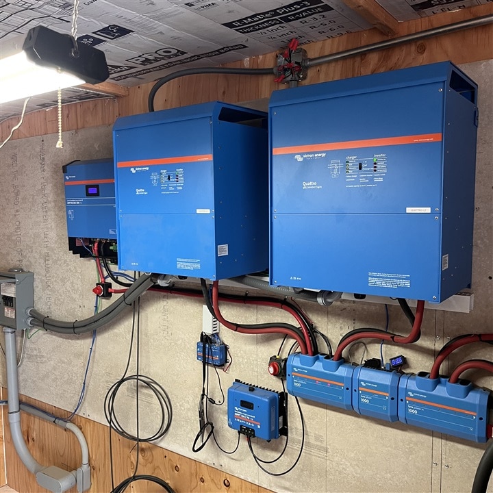
IMAGE TITLE: THEN IMAGE DESCRIPTION |
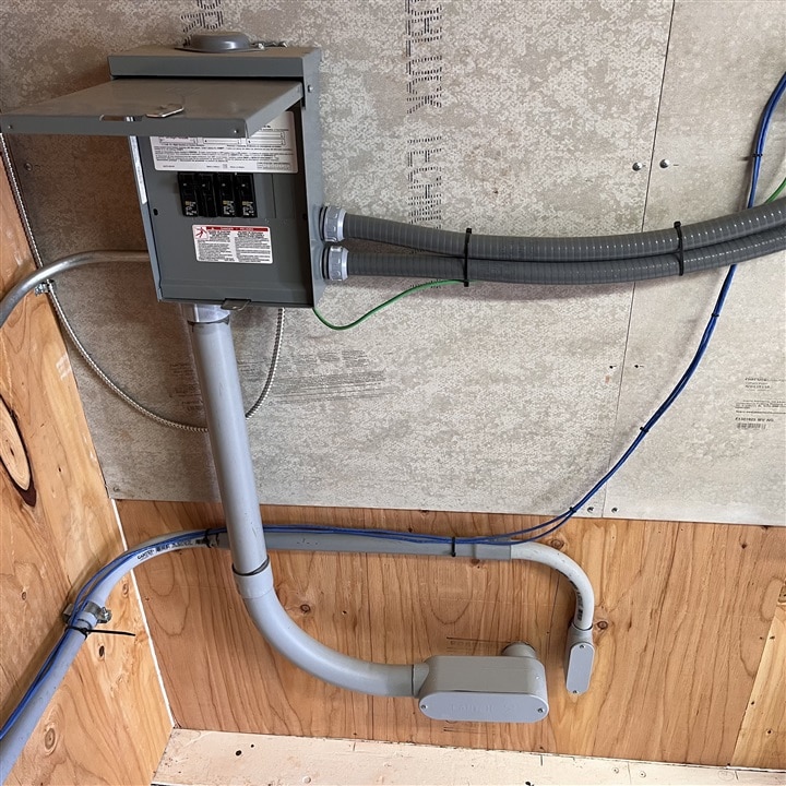
IMAGE TITLE: THEN IMAGE DESCRIPTION |
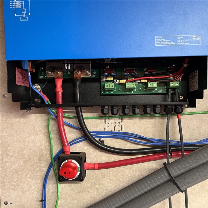
IMAGE TITLE: THEN IMAGE DESCRIPTION |
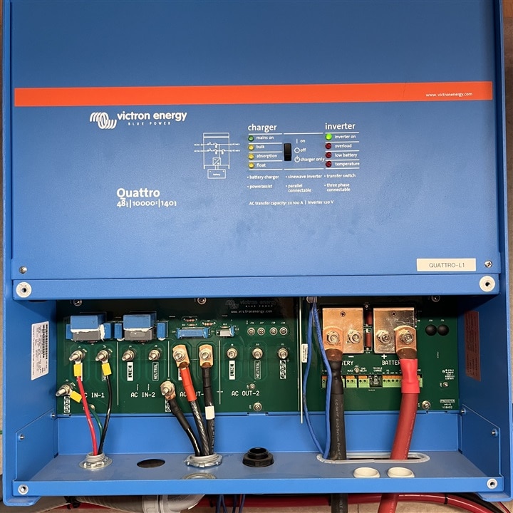
IMAGE TITLE: THEN IMAGE DESCRIPTION |

IMAGE TITLE: THEN IMAGE DESCRIPTION |
Thanks for sticking with me on this journey! More to come, the shop is the next big project, with a couple of video projects as well!
-Kaleb

