


A stubborn logic-level problem inspired Clem to build his own modular lab equipment. His Analog Bridge combines 32 channels of analogue measurement with Ethernet, USB, SCPI control and Python software, creating a versatile logic monitor and seriously slow oscilloscope for tracking down tricky electronics faults. See how it works, where its limitations lie, and how it can help hunt down problems across an entire signal chain.
Build with Clem
A frustrating debugging problem with a homemade PLC gave Clem Mayer an excuse to build another piece of laboratory equipment. While developing the PLC, he found himself trying to establish whether an I/O pin was actually reaching the logic level it was supposed to. The fault was eventually found almost by accident: the signal was changing, but it was not getting far enough electrically to be interpreted correctly by the next device.
“For debugging purposes, having that binary state is not enough. We need to know how high and how low it goes because there's a cutoff point in between... We need to know exactly at which level that signal currently is.”
That different between a logical state and the underlying analogue voltage became the starting point for the project. A conventional logic analyser can tell you an enormous amount about transitions and digital protocols, but Clem wanted something slightly different: lots of channels, the actual measured voltage for each one, software control and enough flexibility to observe an entire signal chain at once.
His answer is the Analog Bridge, a modular 16-channel measurement instrument which can be multiplied as required. For this build, two modules share a case to provide 32 inputs, but they remain independent instruments, complete with their own Ethernet connections. The result sits somewhere between a logic probe, data-acquisition system and a deliberately very slow oscilloscope, with a SCPI interface tying the whole lot into the rest of Clem's lab.
Why measure logic with an ADC?
For a nominal 3.3 V digital system it is tempting to think of every signal as simply 0 V or 3.3 V. Reality is rather less tidy. Digital inputs recognise voltage ranges, and a problematic output may change without travelling sufficiently far into the valid high or low region. A binary indication can therefore hide precisely the information needed while debugging a marginal circuit.
Analog Bridge consequently measures voltages rather than deciding in firmware whether a pin is high or low. That distinction is important. The hardware collects the value; it is the client application that decides how to interpret it.
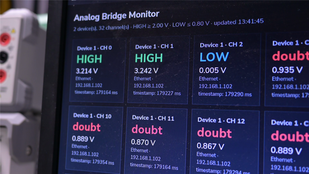
The supplied monitor, for example, uses configurable thresholds. Its defaults classify 2.0 V and above as HIGH, 0.8 V and below as LOW, with anything between those values reported as a doubtful state. Those levels live in the Python application rather than being hard-coded into the measurement hardware, so a user can change the interpretation without changing the instrument firmware.
DEFAULT_HIGH_V = 2.0
DEFAULT_LOW_V = 0.8
DEFAULT_GAIN_V = 4.096
DEFAULT_POLL_SECONDS = 0.25
That approach gives Clem considerably more information than a row of binary logic indicators. He can inspect the measured voltage itself, change the thresholding for a particular circuit and identify signals which sit awkwardly between two valid states.
“The point is I can probe every point in the signal chain to see if it deviates from what I'm expecting to see at any of these points, which means I can determine where the problem is in the chain.”
Because the values remain analogue, the same hardware can also be used for rather more than checking logic. Clem points out that measurements at different places in a circuit can provide information useful for calculations such as Ohm's law, while the host can log, plot or otherwise process the acquired voltages.
16 channels at a time, with as many modules as required
A single Analog Bridge PCB has 16 analogue inputs. Rather than producing a monolithic 32-channel board, Clem simply built two and installed them in the same enclosure. They share power, but not their Ethernet interfaces.
“This is actually two units inside one case. So this is a modular device, meaning I can have as many channels as I may need for my project.”
There is a practical advantage to that architecture beyond easier PCB reuse. Each module is an independently addressable network instrument, so one can be used by one diagnostic application while another performs a different job. There is no internal Ethernet switch or master board coordinating the pair.
This also avoids squeezing the entire 32-channel workload through one acquisition scheduler. Two modules can make measurements independently, with the resulting data reconciled by software. Clem's firmware attaches a millisecond timestamp to each valid sample, and that timing information accompanies the raw ADC value when all 16 channels are requested.
struct Sample {
  uint32_t timestampMs;
  int16_t value;
  bool valid;
};
There is an important detail for anyone extending this idea: these are device-relative timestamps, not globally synchronised wall-clock timestamps. The host oscilloscope application establishes a starting timestamp for each bridge and works with the elapsed time. They are therefore useful for reconstructing and analysing samples, but should not be mistaken for a precision common timebase shared between instruments. The project repository similarly describes the millisecond timestamp as relative to device boot.
“What we're doing is not speed measurements in real time, we're doing data acquisition and then we're plotting the data to analyse it.”
This is a useful way to think about the whole project. Analog Bridge is primarily a many-channel acquisition tool, not a substitute for high-bandwidth test equipment.
The analogue signal path
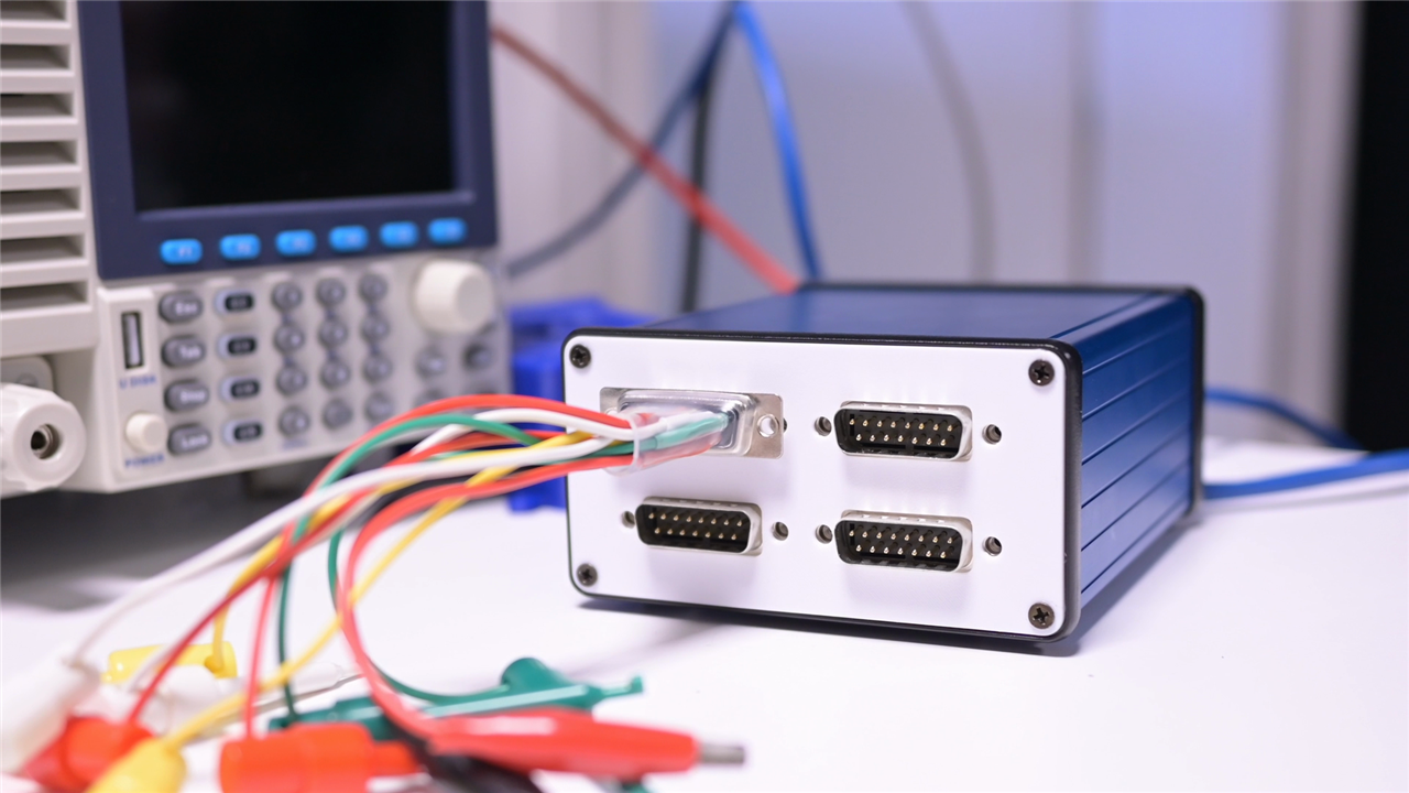
Starting at the business end, Clem chose the familiar 15-pin D-sub connector for the analogue connections. Its relative rarity on modern equipment is actually useful here because there is less chance of accidentally confusing the custom measurement connection with a contemporary computer interface.
More importantly, it provides a convenient point from which to build application-specific leads. A harness can terminate in individual wires or clips, while a little adapter board can present BNC sockets and allow conventional oscilloscope probes or other test equipment to be used.
“This gives me the ability to adapt to whatever I'm testing without modifying my device heavily.”
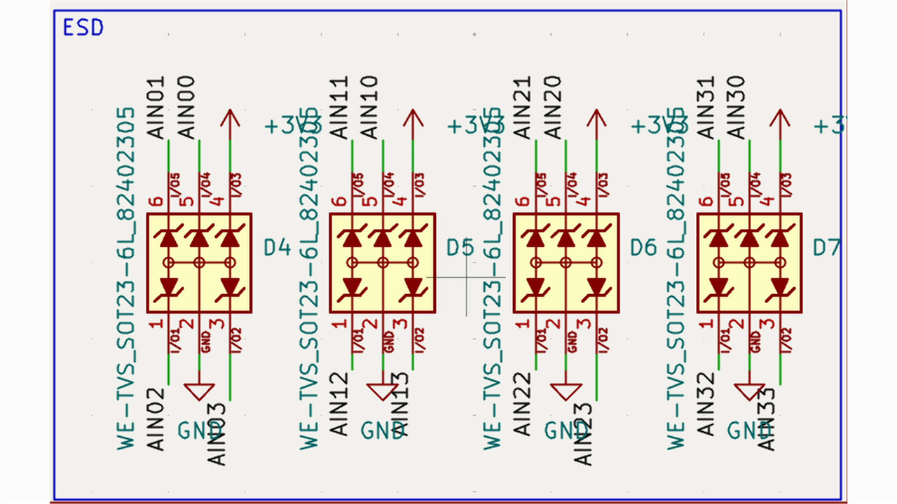
Behind the connector sits the part of the design Clem regards as particularly important: input protection. A bench instrument cannot assume that every circuit connected to it will stay politely within the ADC's range. Static discharge, wiring mistakes, negative voltages and signals from other voltage domains all need consideration.
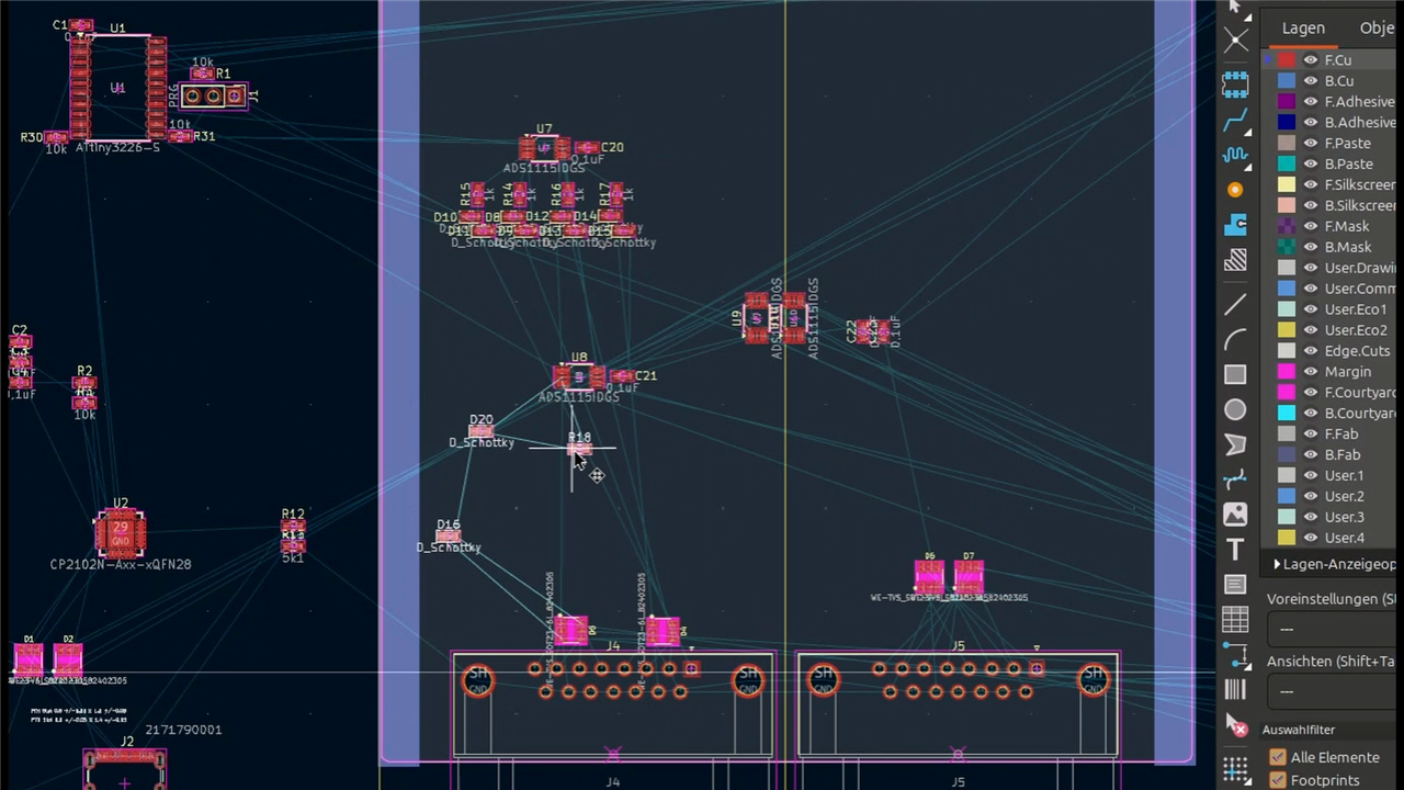
The inputs therefore use Schottky-diode clamps towards 0 V and 3.3 V, together with current-limiting resistance and ESD protection. There are two clamp diodes for each of the 16 channels, so even before the protection around the other interfaces is counted, the little board becomes surprisingly diode-heavy.
“It will always be clipped at zero volts and at 3.3 volts, so it never goes beyond these two points to protect the input chain.”
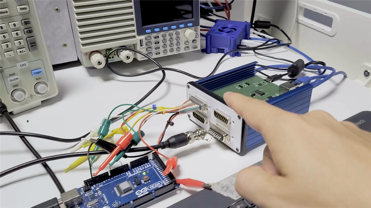
Clem even demonstrates the point with a 5 V Arduino Mega signal. The Analog Bridge itself is intended around a 3.3 V measurement domain, but the protected input limits what reaches the ADC. That should not be interpreted as an invitation to connect arbitrary voltages: the inputs are neither isolated nor a replacement for the rated front end of a proper oscilloscope. Builders should verify the permitted input conditions, common grounding and protection-component ratings before attaching an unknown circuit.
That caution is particularly relevant because this is experimental bench equipment. Clem notes that a productised version would warrant substantially more work around EMC, shielding and signal integrity. His enclosure uses 3D-printed end plates; he experimented with metal parts but found the simpler arrangement adequate for his current use.
Four ADS1115s make the measurement engine
Each module contains four Texas Instruments ADS1115 ADCs, with each converter contributing four single-ended inputs. They occupy I²C addresses 0x48, 0x49, 0x4A and 0x4B, mapping neatly onto logical channel groups 0-3, 4-7, 8-11 and 12-15.
The ADS1115 is a 16-bit delta-sigma ADC with a programmable gain amplifier, four single-ended or two differential inputs and programmable data rates between 8 and 860 samples per second, making it a sensible fit for this sort of low-speed multi-channel acquisition rather than high-bandwidth oscilloscope work.
Clem's firmware exposes those supported rates through its channel configuration while normalising a requested value to a rate the ADS1115 actually supports:
const uint16_t supported[] = {8, 16, 32, 64, 128, 250, 475, 860};
The default configuration is a much more relaxed 16 samples per second. Each logical channel carries its own enabled state, requested rate, sampling period and next-due time. The scheduler then works around the four ADCs, starting a due conversion on an available converter and recording its result when complete.
That implementation detail explains an apparent contradiction in a many-channel ADC system. An ADS1115 may support conversion rates as high as 860 SPS, but four inputs behind a converter still share its multiplexer and converter. Asking every channel to run flat-out cannot magically produce sixteen independent 860 SPS streams. The requested rates are scheduling targets, and the timestamps tell the client when samples were actually obtained.
if (channelConfig[channel].enabled &&
    static_cast<int32_t>(now - channelConfig[channel].nextDue) >= 0) {
  ads[device].setDataRate(adsRate(channelConfig[channel].rate));
  ads[device].startADCReading(ADS_SINGLE_MUX[input], false);
  activeChannel[device] = channel;
}
The ADS1115 ALERT/RDY outputs are also routed back to the ATtiny3226. The firmware can check conversion completion, while retaining a timeout so that a failed or disconnected ADC does not permanently stall its scheduler. That recovery path is the sort of small implementation detail that becomes very useful when an instrument is intended for debugging other unreliable hardware.
For anyone experimenting with the ADS1115 separately, the element14 Community has already explored the converter in data-acquisition applications, including continuous sampling and its conversion-ready signal. There is also an existing Community project adding SCPI control to an ADS1115-based Raspberry Pi Pico acquisition board, useful background reading for anyone interested in taking the instrument-control idea further.
A deliberately modest controller
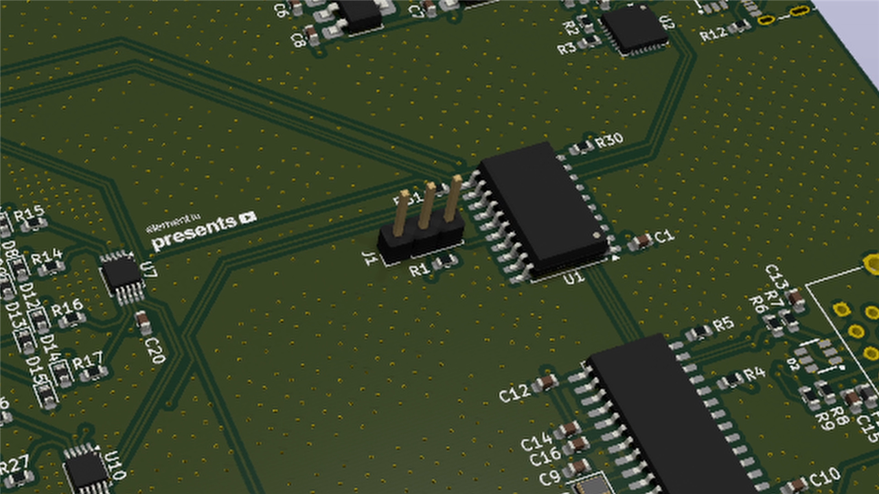
The converters communicate over I²C with a Microchip ATtiny3226. It is a rather more modest processor than somebody might expect to find in a modern oscilloscope, but that is the point: Analog Bridge is not trying to digitise and process high-speed waveforms locally.
The ATtiny3226 is an 8-bit tinyAVR 2-family device capable of running at up to 20 MHz, with 32 KB of Flash and 3 KB of SRAM. Clem chose it because it has the interfaces and pins needed by the application without adding unnecessary computing power.
“The MCU only relays data. It doesn't do any signal processing on here... it just obtains that data and then whenever asked for it, it will relay that over Ethernet.”
This decision keeps the embedded side pleasingly straightforward. Interpretation, graphing and logic-state classification all happen on the host. Improvements can therefore be made to the applications without repeatedly rebuilding the measurement hardware.
Ethernet, USB and SCPI
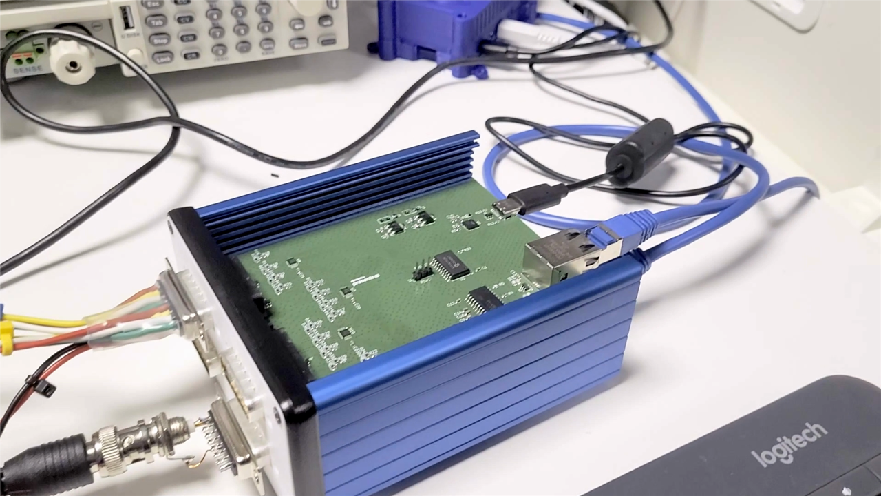
The ATtiny's next job is getting those samples off the instrument. Ethernet comes courtesy of the familiar ENC28J60 controller. Clem had already used the part in his EtherRGB project, so this was an opportunity to reuse a proven portion of the design rather than solving the same networking problem again.
USB uses a Silicon Labs CP2102N USB-to-UART bridge. The USB connection is deliberately an instrument interface rather than the normal firmware-programming path. Clem keeps UPDI available for deliberate firmware updates instead of turning the externally accessible USB connector into a convenient route for reflashing the controller.
“This is strictly a UART connection that can have debug output but also will accept SCPI commands. So you can choose if you're going via Ethernet or USB.”
The two interfaces expose the same simple command-oriented model. Ethernet uses DHCP and TCP port 5025, while USB serial operates at 115200 8N1. The current project documentation notes that the network service has neither authentication nor encryption, so Ethernet operation belongs on a trusted network rather than an exposed one.
Clem implements the subset of SCPI commands the instrument actually needs. *IDN? identifies the unit, *RST restores the default channel setup, SYST:ERR? exposes the last command error, configuration commands control channel state and rate, and MEAS:RAW? or MEAS:RAW:ALL? retrieve readings.
if (command == F("MEAS:RAW:ALL?")) {
  for (uint8_t channel = 0; channel < CHANNEL_COUNT; ++channel) {
    writeChannelStatus(output, channel);
  }
  return;
}
An all-channel response contains the channel number, enabled state, configured rate, raw ADC result and timestamp. That provides a compact interface which is easy for scripts to consume while retaining the acquisition metadata needed for later analysis.
The idea of a home-built SCPI instrument also has some useful precedent on the element14 Community. A previous ADS1115-based data-acquisition project was given SCPI firmware specifically to make custom hardware easier to use alongside standards-based laboratory automation. Analog Bridge takes a similar philosophy and applies it to a modular, networked multi-channel tool.

Keeping the modules independent
The dual-module configuration creates a power consideration which is easy to overlook. Both boards are linked for power so a single USB-C connection can supply the assembly, but connecting multiple powered interfaces can create potentially unpleasant back-power paths towards another module or the host computer.
Clem consequently includes diode protection around the power inputs to prevent current travelling in the wrong direction. In his view, this and the analogue input protection account for a surprisingly substantial part of the electrical design.
The finished boards live in a Hammond 1455-series enclosure. The series lends itself well to sliding PCBs into an aluminium extrusion, and using a larger version leaves a straightforward route to fitting more modules. The front and rear plates for this build are 3D printed, with the project's manufacturing assets including the required 3MF and SVG files.
Turning 32 voltages into a logic monitor
Once the hardware is measuring, the client software is where the project becomes particularly flexible. Clem's Python monitor first searches for Analog Bridge devices and identifies them using the normal *IDN? request. Ethernet discovery probes the local IPv4 /24 networks for devices listening on port 5025. USB discovery can alternatively probe serial interfaces using PySerial.
Once discovered, the program repeatedly asks each instrument for all 16 measurements:
channels = parse_measurements(
    device,
    device.command("MEAS:RAW:ALL?", 16)
)
The raw signed ADC value is converted using the configured ±4.096 V full-scale setting, after which the host applies its HIGH and LOW thresholds. With two bridges attached, the browser interface consequently becomes a 32-channel logic-level monitor showing both interpreted state and measured voltage.
This directly addresses the original PLC problem. Instead of moving a probe from node to node and trying to mentally correlate what happened earlier, Clem can wire probes throughout the signal path and observe the system together.
“I can go through my device's states, see if the signal changes have occurred as they should... I can see if the signal chain has propagated correctly.”
The ability to configure thresholds is particularly handy here. It prevents the instrument itself from asserting that an arbitrary voltage is universally a valid digital HIGH or LOW. The host can use limits appropriate to the circuit being investigated, while still displaying the underlying measurement when something sits in the grey area.
The world's slowest eight-channel oscilloscope?
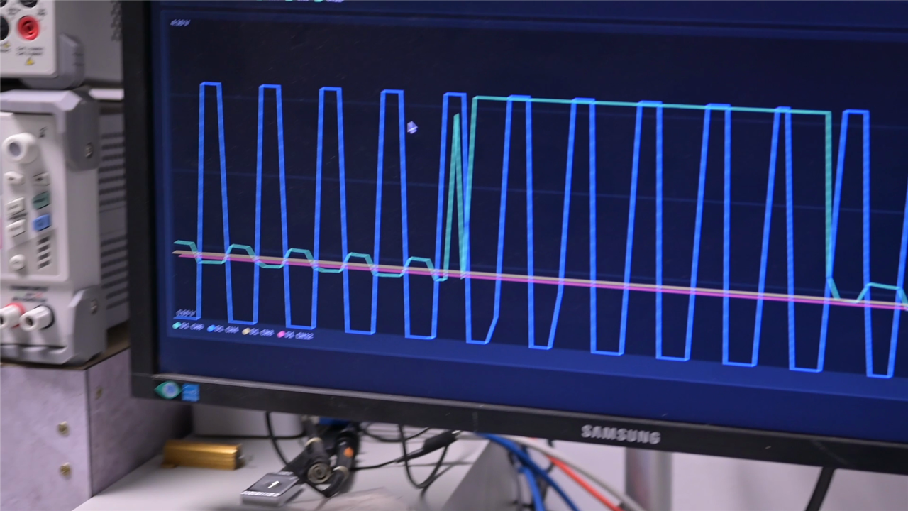
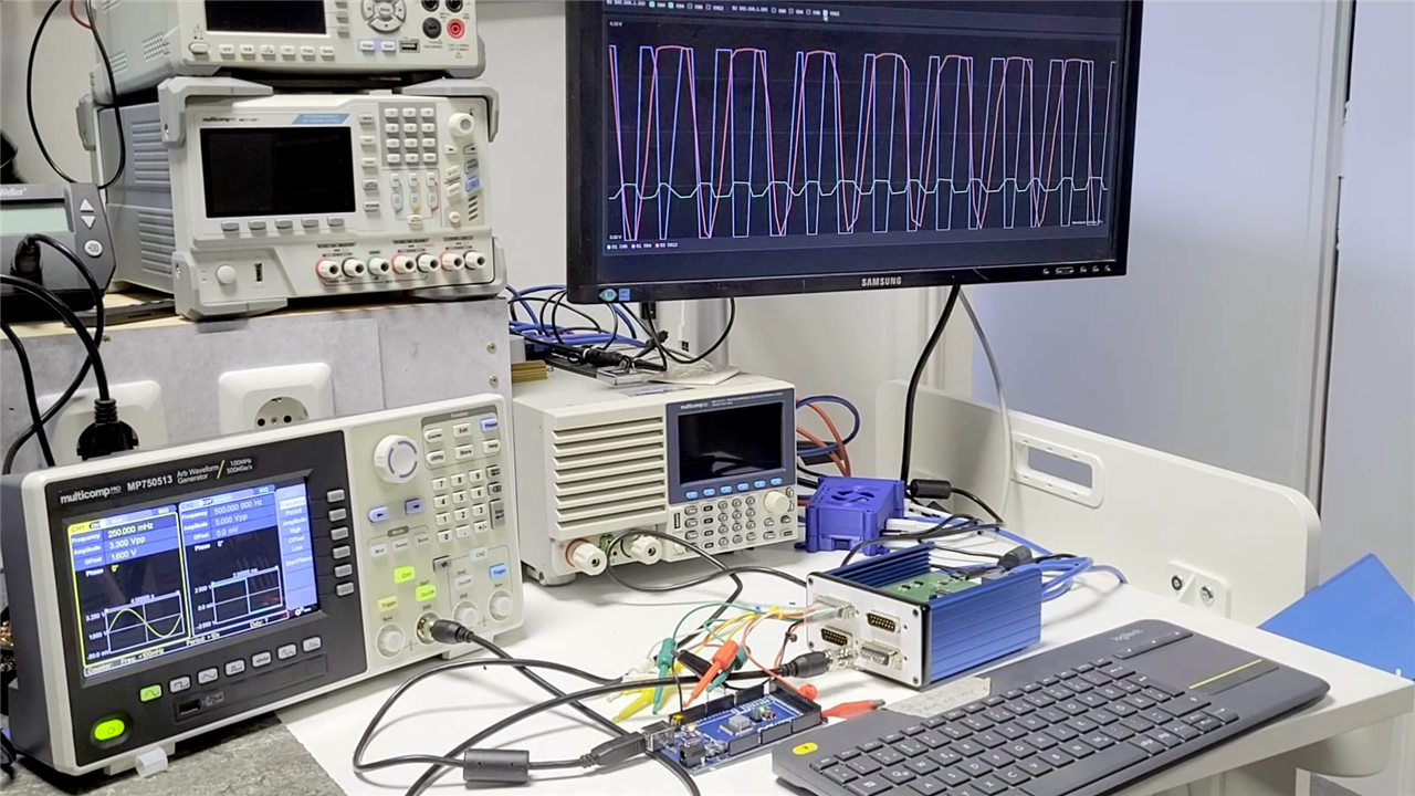
The second Python application deliberately pushes the same hardware into territory for which it was never really intended. It plots one input from each ADS1115, logical channels 0, 4, 8 and 12, giving four traces per module. With two bridges, that makes an eight-trace waveform display.
It is described, with suitable enthusiasm, as an oscilloscope. Clem is equally quick to point out that it is not a particularly good one.
“Technically we have made an oscilloscope now with eight channels... so we have an eight-channel oscilloscope that is very slow.”
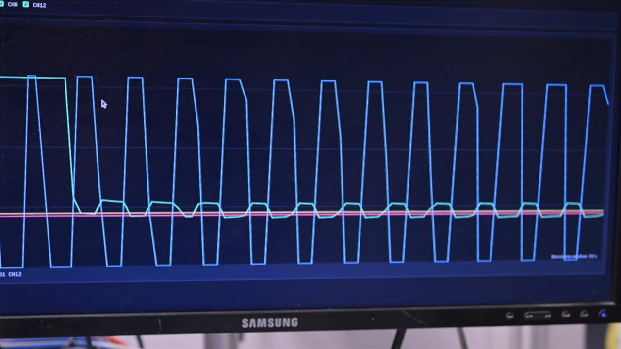
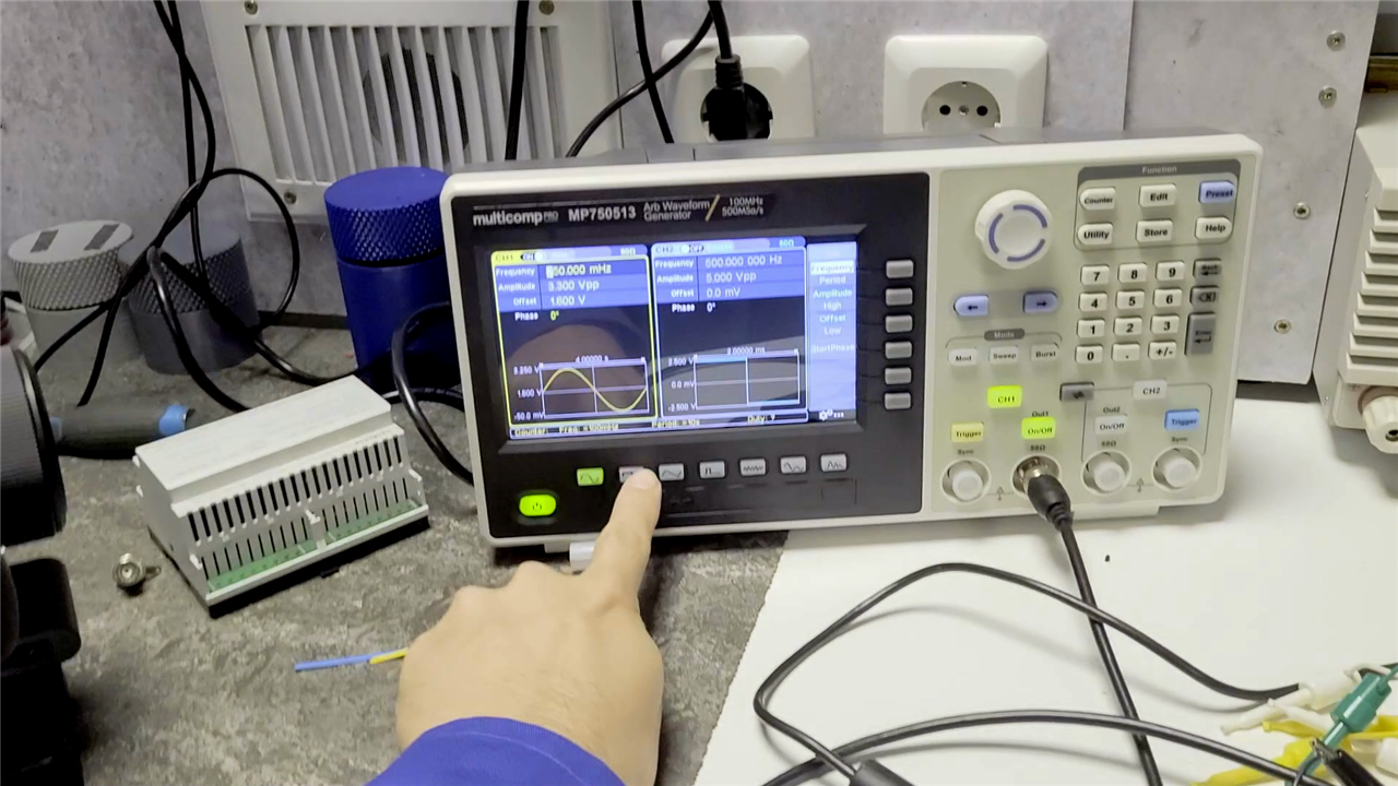
The host defaults to polling every 250 ms and plots measurements into a rolling 30-second window. As the test frequency is increased, the acquisition rapidly stops representing the original waveform. Samples become isolated points along a much faster signal and there simply is not sufficient information to reconstruct the curve correctly.
For Clem's demonstration, getting down below about 1 Hz is where complete slow waveforms such as sine and sawtooth signals become recognisable. This limitation should not be confused with the headline 860 SPS capability of an individual ADS1115 configuration. The complete instrument includes input multiplexing, channel scheduling, command-and-response transfer, host-side polling and plotting. The demonstration is therefore illustrating the behaviour of this complete multi-channel system, rather than simply quoting the converter's maximum specification.
The supplied oscilloscope client reinforces the distinction. It concentrates on channels 0, 4, 8 and 12, AIN0 on each converter, rather than pretending that every input can simultaneously behave like an independent high-speed scope channel.
“It is a logic probe. It tells us the state of a pin at a given time and not the transition between those states, so different tools for different purposes.”
It also makes a neat practical demonstration of why a proper oscilloscope costs rather more than an ADC and a microcontroller. Capturing a faithful fast waveform requires a high-rate analogue front end, sustained acquisition bandwidth, buffering, processing and display. Analog Bridge instead trades that performance for many inexpensive channels and software flexibility.
What's inside the build?
The bill of materials reflects the modular approach. Across the 32-channel build there are eight Texas Instruments ADS1115IDGST ADCs, two ATtiny3226-SU microcontrollers, two ENC28J60 Ethernet controllers and two CP2102N USB-to-UART bridges, alongside the Ethernet magnetics, protection, passives, regulators and connectors.
Farnell order code 3116563, the ADS1115IDGST, is a 16-bit delta-sigma converter offering four single-ended inputs, I²C, a programmable gain amplifier and selectable data rates from 8 to 860 SPS. It operates from 2 V to 5.5 V and provides four pin-selectable I²C addresses, which is particularly convenient here: putting four of them on a single bus is precisely what gives each Analog Bridge module its 16 inputs.
Farnell order code 3872794, the ATtiny3226-SU, supplies considerably more capability than the project needs for raw computation while remaining an inexpensive controller. It supports operation up to 20 MHz and includes 32 KB Flash, 3 KB SRAM plus I²C, SPI and serial interfaces. The Analog Bridge firmware makes practical use of all three communication directions: I²C talks to the ADCs, SPI connects the Ethernet controller and UART provides the USB-facing SCPI channel.
The BOM also specifies the Hammond 1455 enclosure, MH Connectors D-sub hardware, a Microchip 3.3 V regulator and the assortment of decoupling, filtering and protection components required to turn the main ICs into something useful on a test bench.
Firmware designed to be debugged
There is another useful inclusion for anyone recreating the project: the repository contains separate ADC diagnostic firmware in addition to the normal instrument application. Rather than involving Ethernet, SCPI, Python and the acquisition scheduler all at once, adc-test.cpp probes the four expected I²C addresses and directly reports raw conversions.
constexpr uint8_t ADS_ADDRESSES[4] = {0x48, 0x49, 0x4A, 0x4B};

for (uint8_t device = 0; device < 4; ++device) {
  adsPresent[device] = ads[device].begin(ADS_ADDRESSES[device]);
}
That provides a much better starting point if a freshly assembled board cannot see one of its converters. Power, I²C wiring and address configuration can be established before adding the networking and host-software layers. The repository documents a dedicated PlatformIO ADC_TEST environment for exactly this purpose.
A platform rather than a single-purpose instrument
The most successful aspect of Analog Bridge is arguably that Clem has resisted making the hardware overly clever. The modules measure voltages, maintain some per-channel acquisition configuration, timestamp the resulting samples and make those results accessible using a familiar command structure. Almost everything application-specific happens elsewhere.
Today that application might be the 32-channel monitor which finally solves the PLC debugging problem. Another session might call for logging several slowly changing analogue signals, comparing events across different parts of a machine or displaying a handful of channels as waveforms.
The open hardware aspect makes the idea similarly extensible. The published project contains the PlatformIO firmware and Python host applications together with the KiCad PCB and schematic sources, 3D-printable enclosure parts and other manufacturing files. Clem's GitHub repository describes the project as work in progress, leaving plenty of room for further refinement.
There are some obvious directions in which a more ambitious version could go. A production instrument would deserve more careful EMC and shielding work, greater attention to front-end signal integrity and perhaps isolation or a more sophisticated input stage. Equally, improving acquisition architecture would be necessary before trying to push substantially further into oscilloscope territory.
But speed was never the central problem here. The design is deliberately biased towards channel count, accessibility and the ability to interrogate those channels programmatically.
“In electronics design there are countless questions to answer all the time, and most of them are debugging and hunting ghosts. So why not... make the dedicated test equipment that you need for your job yourself?”
That leaves Analog Bridge as a particularly maker-friendly piece of lab equipment. It grew from a real debugging nuisance, uses affordable and familiar parts, speaks a protocol that lets it sit alongside conventional instruments and delegates most of its clever behaviour to software that can be changed whenever the next debugging job demands something different.
Project files and further reading
- Episode 736 Resources - DIY Test Equipment: Building a Modular 32-Channel Python SCPI Logic Monitor – firmware, Python host tools, KiCad design files and manufacturing assets.
- element14 presents – more projects and builds from Clem and the other element14 Presents hosts.
- Data Acquisition Board for Pi Pico – an element14 Community ADS1115 data-acquisition project.
- SCPI firmware for the Pico Data Acquisition Board – another approach to building standards-friendly homemade test equipment.
- Continuous sampling with the Data Acquisition Board for Pi Pico – further Community exploration of ADS1115 sampling and its ready signal.
Bill of Materials and Parts Used
| Product Name | Manufacturer | Quantity | Buy Kit |
|---|---|---|---|
| ADS1115IDGST | TI | 8 | Buy Now |
| CP2102N-A02-GQFN28 | silicon labs | 2 | Buy Now |
| MHDB15SS | MH connecotrs | 8 | Buy Now |
| 1455 Case | Hammond | 1 | Buy Now |
| ATTINY3226-SU | microchip | 2 | Buy Now |
| ENC28J60-I/SO | microchip | 2 | Buy Now |
| MCSJK-7E-25.00-8-10-60-B-10 | multicomp pro | 2 | Buy Now |
| P01-0002-01 Magjack | Bel | 2 | Buy Now |
| MMZ1608Y152BTA00 | TDK | 2 | Buy Now |
| MCT06030D4999BP500 | vishay | 10 | Buy Now |
| C0603C104K3RACTU | yageo | 10 | Buy Now |
| ERJ3EKF2321V | panasonic | 2 | Buy Now |
| GRM188R60J106ME47D | murata | 10 | Buy Now |
| MCWR06X3300FTL | multicomp pro | 4 | Buy Now |
| MC0201N120J250CT | multicomp pro | 4 | Buy Now |
| MCP1825s 3V3 | microchip | 4 | Buy Now |
Additional Parts
| Product Name | Manufacturer | Quantity |
|---|---|---|
| DB15 male receptacles | ||
| various resistors and caps, |

