


Charge Up with Robin!
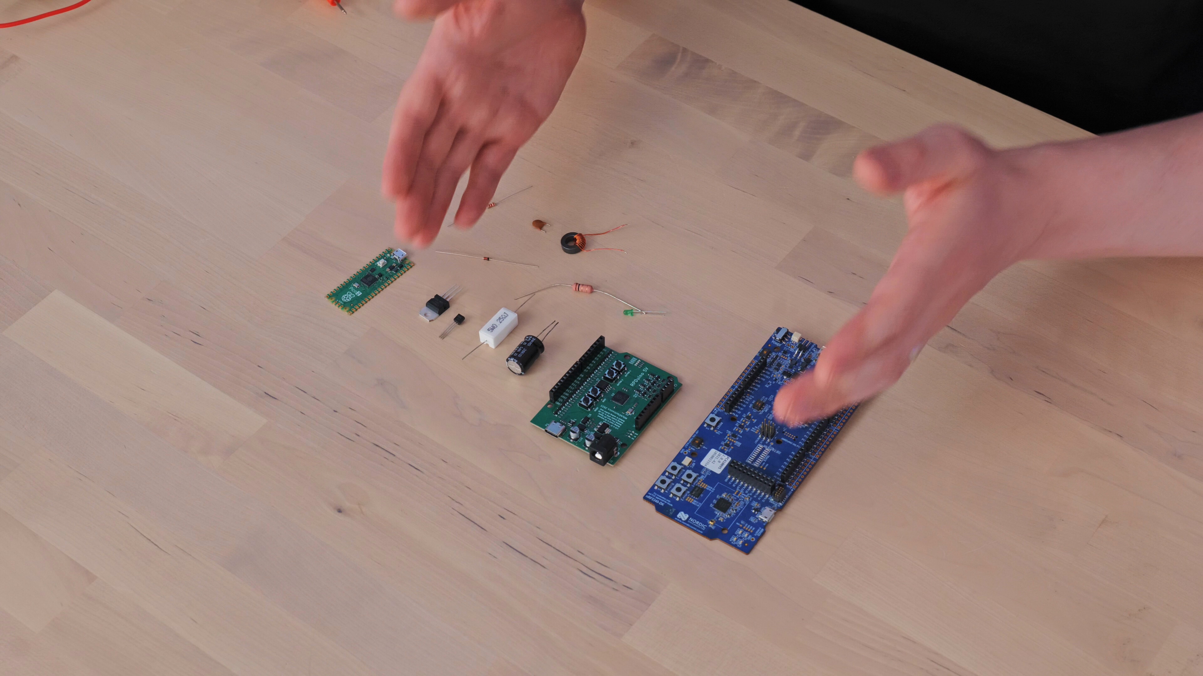
Electronics can quickly become a world of integrated circuits, microcontrollers, sensors, transistors and thousands of increasingly specialised components. Before getting lost amongst all of those parts, however, it helps to understand three much simpler building blocks: the resistor, capacitor and inductor.
Following his introduction to electricity, voltage, current and ground, Robin continues his introduction to electronics by concentrating on these three passive components. They appear throughout electronic design, from a simple LED circuit to power supplies, filters, amplifiers and radio-frequency systems.
“Of all the components we use in electronics, there are three that are absolutely fundamental… and they are the resistor, the capacitor and the inductor.”
Robin affectionately calls them the “Holy Trinity” of components, and even gives them a suitably over-the-top musical introduction. Behind the joke is a useful way of organising some important ideas. A resistor restricts current and dissipates energy; a capacitor stores energy in an electric field and resists rapid changes in voltage; an inductor stores energy in a magnetic field and resists rapid changes in current.
Starting with resistance and Ohm’s law
The resistor is Robin’s starting point because its basic behaviour is comparatively straightforward. A resistor has two terminals separated by resistive material. As charge moves through it, the material provides resistance to the flow of current.
Robin illustrates this with people walking through a corridor. A very narrow corridor restricts the number of people able to pass at once, while a wide corridor lets many more through. Increasing the resistance in an electrical circuit similarly reduces the current that can flow for a given applied voltage.
Resistance is measured in ohms (Ω), while current is measured in amperes (A). For the small circuits a beginner is likely to encounter, current will frequently be expressed in milliamperes (mA), with 1 A equal to 1,000 mA.
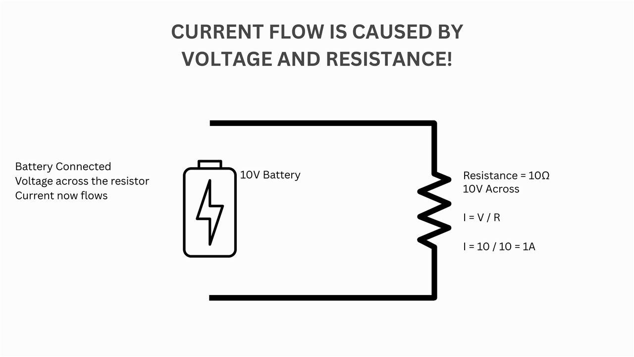
This leads Robin to one of the most useful relationships a beginner can learn:
I = V / R
where I is current in amperes, V is voltage in volts and R is resistance in ohms.
“Voltage, resistance and current are all directly connected. If you know any two of them, you can calculate the third.”
This is Ohm’s law, more conventionally written as V = IR. Robin deliberately rearranges it as I = V/R to encourage a particular way of thinking about a simple resistive circuit: apply a voltage across a resistance and the combination determines the resulting current.
For example, putting 5 V across a 1 kΩ resistor gives:
I = 5 / 1,000 = 0.005 A = 5 mA
That simple calculation becomes useful almost immediately when selecting current-limiting resistors, designing potential dividers and eventually working with considerably more complicated circuits such as operational-amplifier designs.
There is some nuance waiting further down the road. Ohm’s law describes the proportional voltage-current relationship of an ohmic conductor, and real components do not all have a constant resistance under every operating condition. For an introduction to electronics, however, a resistor and Ohm’s law provide an exceptionally useful starting point for understanding what happens when voltage is applied to a circuit.
Capacitors: charge, voltage and electric fields
The capacitor introduces another important idea: circuits can store energy.
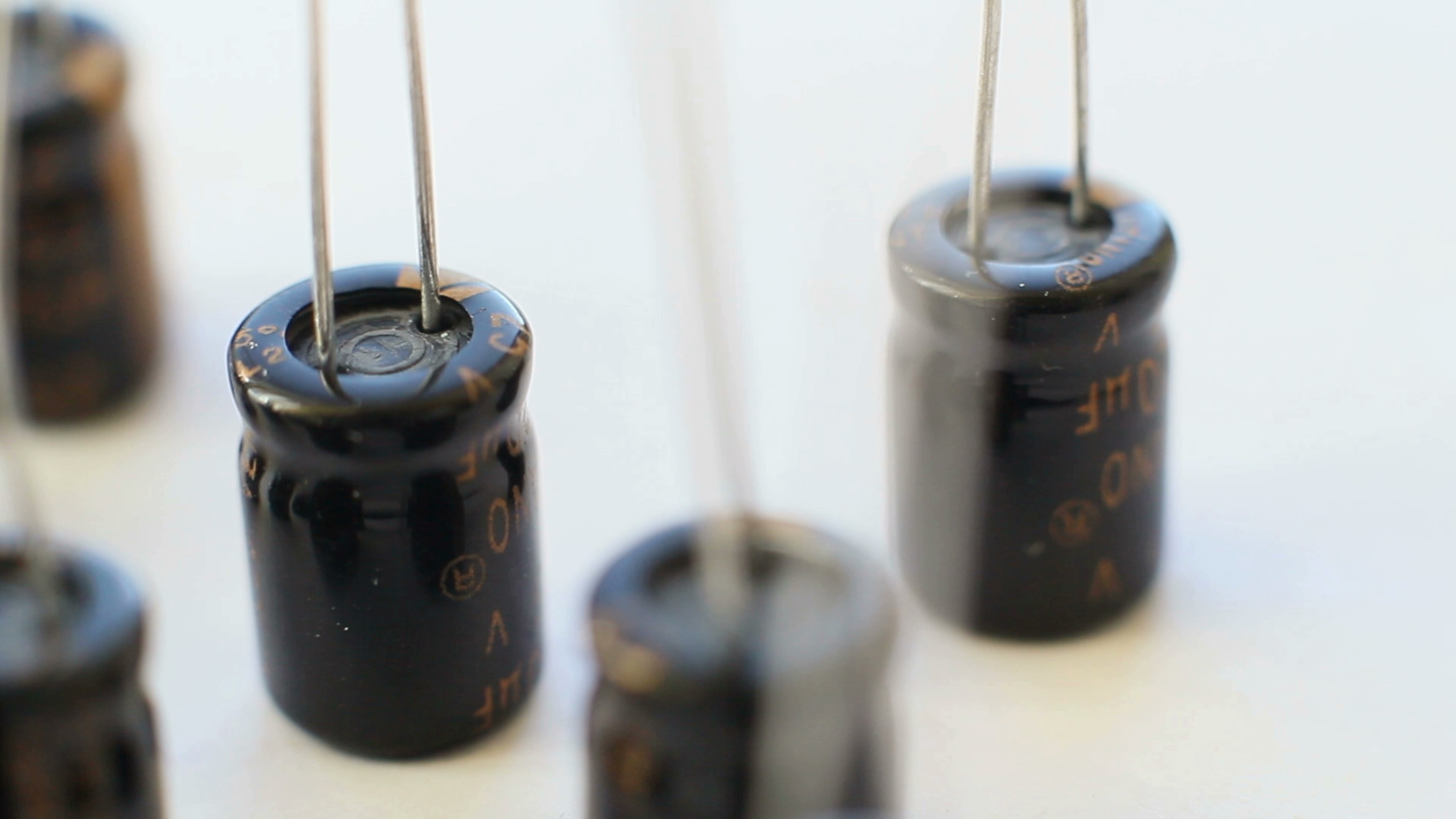
At its simplest, a capacitor can be thought of as two conductive plates separated by an insulating material called a dielectric. Robin demonstrates that the principle does not require an exotic component: two pieces of conductive foil separated by paper already form a rudimentary capacitor.
When a DC voltage is first connected across a capacitor, charge accumulates on its plates. As the capacitor charges, the voltage across it rises towards the supply voltage. Once steady-state conditions have been reached, current no longer flows continuously through the dielectric.
“The important thing is that the two plates are electrically isolated from each other.”
Remove the supply and that separated charge can remain, allowing the capacitor to store energy in its electric field. Connect it into an appropriate circuit again and that stored energy can be released. Unlike a battery intended for comparatively long-duration energy storage, an ordinary capacitor can respond extremely quickly.
The amount of capacitance is measured in farads (F). One farad is very large for many conventional electronic circuits, so beginners will more commonly encounter microfarads (µF) and nanofarads (nF), along with picofarads (pF) as they progress further into electronics. Robin uses a 470 µF capacitor as a tangible example of how physical size does not necessarily correspond to a conveniently large number of farads.
A particularly important use follows directly from this ability to respond quickly. A processor or other digital IC can alter its current demand extremely rapidly as internal circuitry switches. The power source and PCB connections are not ideal and cannot necessarily supply that instantaneous change without some disturbance to the local supply voltage.
A decoupling capacitor positioned close to an IC's supply pins can act as a small local energy reservoir, helping provide transient current and keeping the supply voltage more stable. It is one of those ideas that reappears almost everywhere once someone starts building practical electronic circuits.
Capacitors can also form filters and couple changing signals between parts of a circuit while blocking a steady DC component. Robin deliberately leaves the deeper explanation of capacitive coupling for later, rather than piling frequency, impedance and calculus onto the first explanation of what a capacitor actually does.
“For now, just remember: capacitors store energy in an electric field, they resist sudden changes in voltage, and they can be incredibly useful for filtering, coupling and stabilising electronic circuits.”
Inductors: where electricity meets magnetism
The third member of Robin’s trio is the component he describes as the “weirdest” of the three: the inductor.
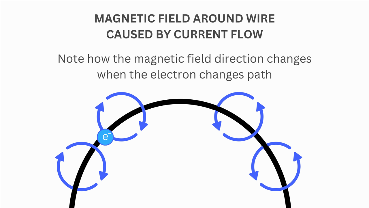
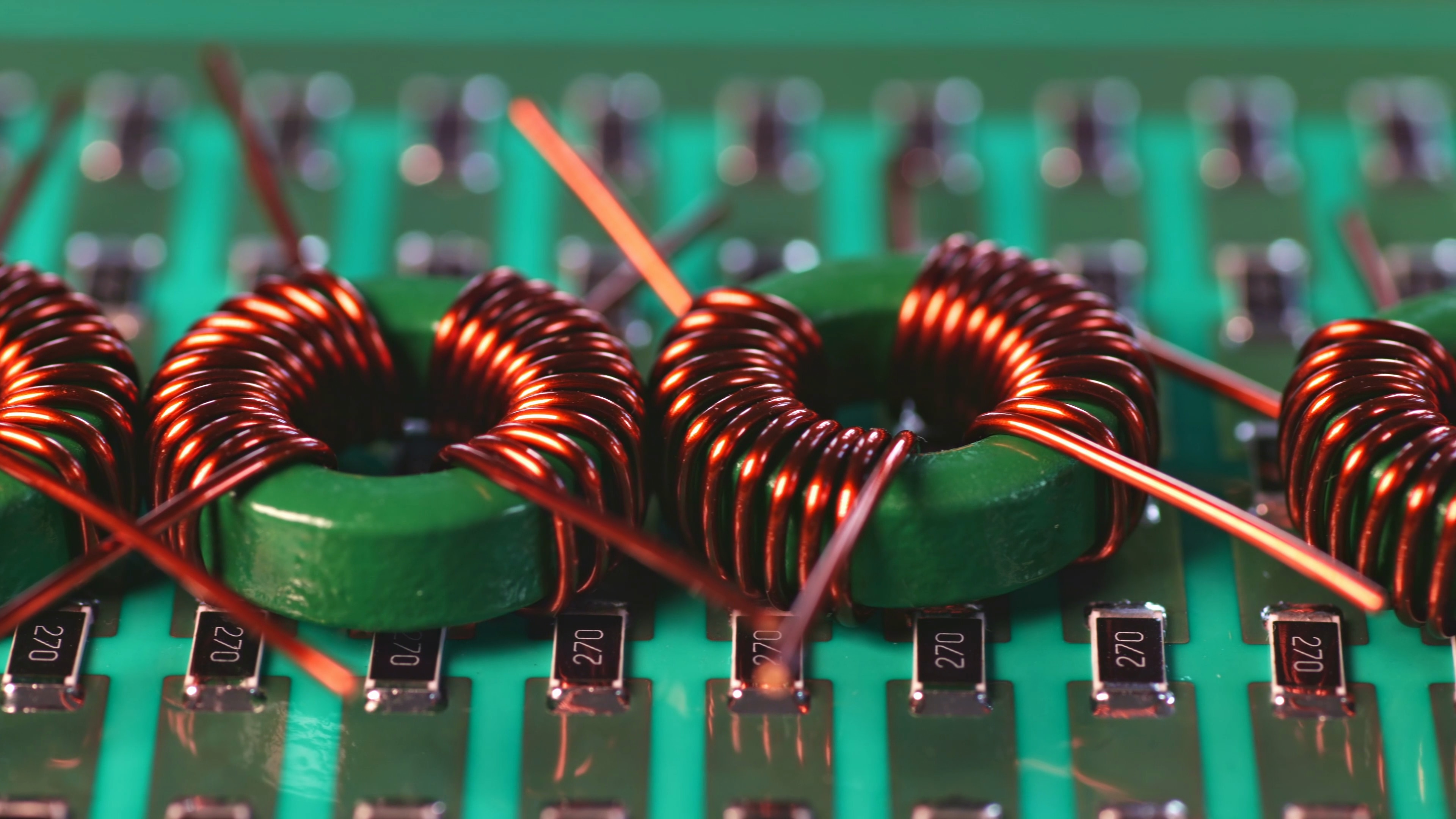
An inductor is commonly formed from a coil of wire, sometimes wound around a magnetic material such as iron or ferrite and sometimes constructed without a magnetic core. Pass current through the winding and it produces a magnetic field. The coiled geometry concentrates that field.
The interesting part begins when the current changes.
An increasing current produces an increasing magnetic field. That changing magnetic field induces a voltage which opposes the change that produced it. Consequently, an ideal inductor resists an abrupt change in current. If the current subsequently becomes constant, the magnetic field also becomes constant and the induced opposing voltage falls away. In a DC steady state an ideal inductor therefore approaches the behaviour of a short circuit, although a real winding still has resistance and other non-ideal characteristics.
“An inductor doesn’t like its current changing suddenly. The faster you try to increase that current, the stronger this opposing voltage becomes.”
The reverse process is equally important. Interrupt the current and the stored magnetic field begins to collapse. That changing field generates a voltage which attempts to keep current flowing. The magnetic energy stored by the inductor is being returned to the circuit.
This behaviour is immensely useful, but it also explains Robin’s warning that inductors can be damaging to a circuit if their stored energy is not handled appropriately. Switching an inductive load can create a large voltage transient as the magnetic field collapses, one of the reasons protection components are often required when switching coils, relays and motors.
Inductance is measured in henries (H). As with the farad, a whole henry is comparatively large for many electronic applications, so millihenries (mH) and microhenries (µH) commonly appear in practical designs.
Inductors have important roles in power electronics and filtering. Together with capacitors they can create frequency-selective and resonant circuits. In RF electronics, carefully chosen inductance and capacitance can create circuits which respond strongly around a particular frequency, providing the underlying principle behind familiar applications such as selecting one radio channel from many occupying different frequencies.
Three components, three useful ways to think
There is considerably more to learn about each component, but Robin's introduction provides three useful mental models to carry forward:
- Resistor: opposes the flow of current and allows current and voltage to be controlled. Resistance is measured in ohms (Ω).
- Capacitor: stores energy in an electric field and resists abrupt changes in voltage. Capacitance is measured in farads (F).
- Inductor: stores energy in a magnetic field and resists abrupt changes in current. Inductance is measured in henries (H).
Those concepts provide a route into much more of electronics. Resistors lead naturally into current limiting and voltage dividers. Capacitors introduce timing, coupling, decoupling and filtering. Inductors connect circuit behaviour with electromagnetism and lead towards power conversion, filtering and RF design. Combining the three eventually leads into RC, RL and RLC networks, frequency response and resonance.
Real components add another layer. Practical capacitors possess equivalent series resistance and inductance, practical inductors have winding resistance, parasitic capacitance and magnetic-core limitations, and even an ordinary resistor acquires parasitic properties at sufficiently high frequencies. Those behaviours become much easier to understand once the ideal versions are familiar.
“These three components are absolutely fundamental to electronics.”
Rather than simply memorising what each component looks like on a schematic, Robin's approach is to understand what it does to voltage, current and stored energy. That gives a beginner something much more reusable when encountering an unfamiliar circuit.
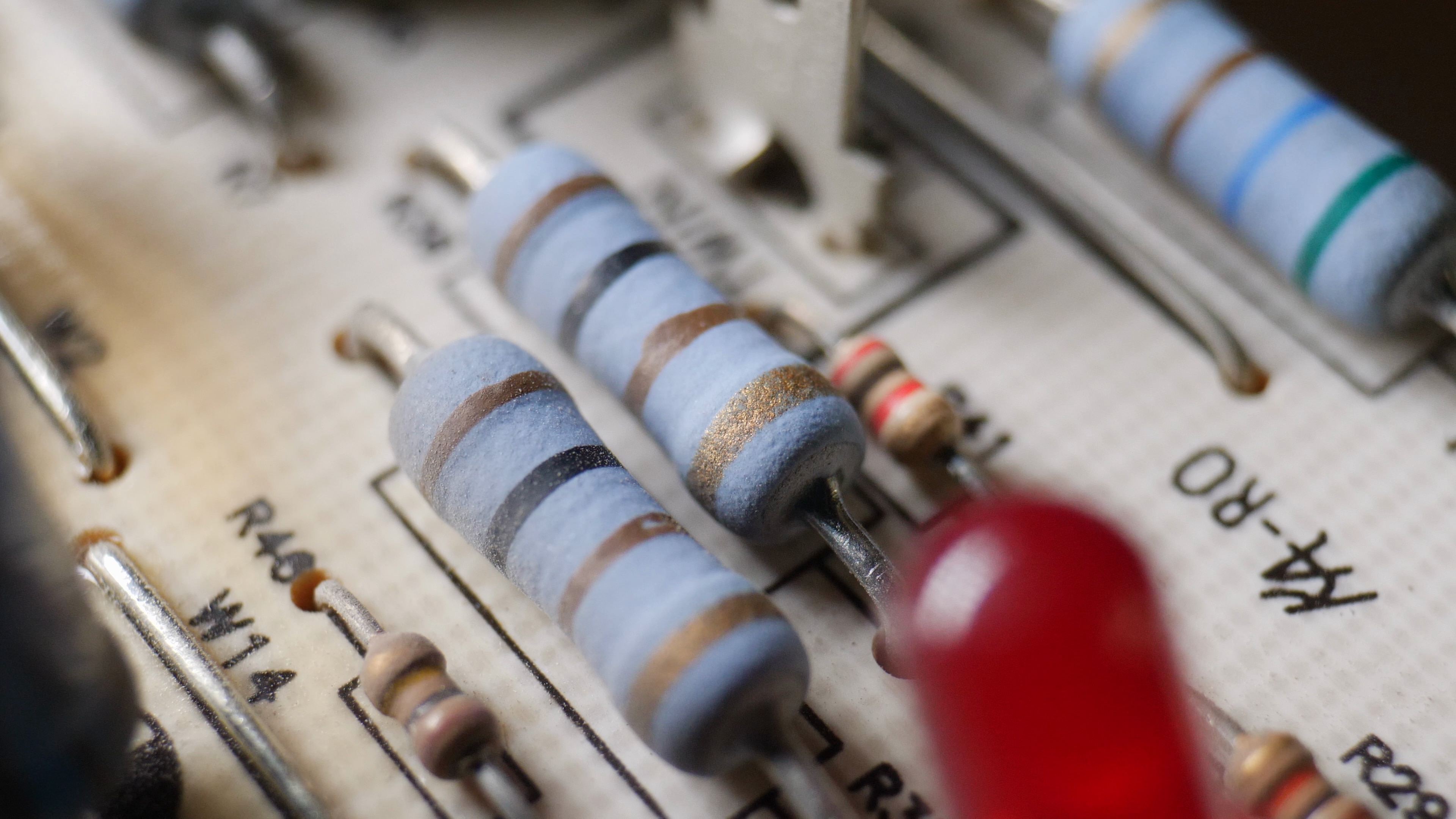
The next step is to take the simplest member of the trio and examine it properly. Robin will return to resistors to explore how they work in practical circuits and, importantly, how to work out the value of the resistor sitting on the bench when all there is to go on is a collection of coloured bands or component markings.
Continue learning
- Fundamentals of Electronics: Understanding Electricity, Voltage and Current – revisit the previous episode covering the electrical concepts used throughout this introduction.
- Passive Components on the element14 Community – explore Community resources covering resistors, capacitors, inductors and their practical applications.
- Decoupling Capacitor Experiments – see the effects of power-supply decoupling investigated in a practical logic circuit.
- Ideal vs Real Inductors: Part 1 – Understanding the Inductor – go beyond the ideal model and explore how practical inductors behave, including their use at RF.
- A Comprehensive Guide to Capacitors – explore capacitor construction, technologies and practical applications in greater depth.
- Ohm's law – additional background on the relationship between voltage, current and resistance.