


What if a pillbox could quietly keep track of when it’s being used, without changing how someone uses it? Miloš hides an ESP32, Hall effect sensors and magnets inside an ordinary-looking pill organiser to detect when each day is opened.
See how it was designed, built and programmed, including the problems uncovered along the way below:
Time to Take your Medicine!
When Familiarity Is Part of the Design
Has Grandma taken her medication? It is a simple question, but answering it becomes difficult when nobody else is at home.
This was the problem Miloš Rašić had been considering for several years. His grandmother uses a conventional weekly pill organiser, with separate compartments for different days and times. It is familiar, straightforward and contains almost nothing that can break. The difficulty is that once the compartments have been filled, family members have no way of knowing whether the correct section has been opened at the expected time.
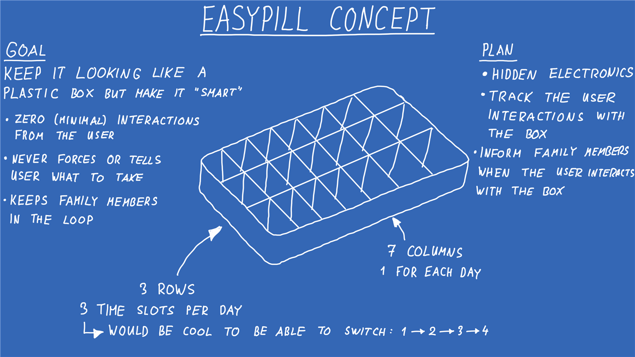
EasyPill V0 explores whether some useful monitoring can be added without replacing that familiar experience. Rather than designing another electronic health product covered in displays, lights and controls, Miloš deliberately set out to make something that would still appear to be an ordinary plastic pillbox.
“I don’t want her to even know whether something is electronics or not. It should look like a simple box.”
The electronics operate in the background. They watch for interactions with the box and make that information available to family members, while the person using it continues to open and close the same kind of compartments they already understand.
EasyPill does not dispense medication, identify tablets or instruct somebody what to take. It is not a medical device and should not be treated as confirmation that a dose has been swallowed. Instead, it is an open-source proof of concept that can detect which daily lid was opened and when. That event can then be checked against a schedule and displayed through a local web interface.
The project follows Miloš’s earlier work on health-monitoring equipment for elderly users. His previous open-source blood-pressure and cardiography project also grew from looking at the practical health needs of his grandmother, while carefully separating experimental electronics from medical-grade equipment. Readers interested in that work can also see Building an Open Source Blood Pressure & Heart Signal Monitor.
Planning a Pillbox with Almost No User Interface
The starting point was a 21-compartment organiser arranged as seven columns, one for each day of the week, with three medication compartments per day. Miloš also wanted the internal tray to be replaceable so the same outer enclosure could support one, two, three or potentially four compartments per day.
That modularity became part of the mechanical design. The printed outer body contains the electronics and lid-detection system, while a removable insert defines the number and size of the medication compartments. Changing the medication arrangement should therefore not require redesigning the electronics.
Several requirements guided the project:
- The pillbox should still look and behave like an ordinary plastic organiser.
- The user should not need to operate an electronic interface.
- The system should monitor interaction rather than decide what medication should be taken.
- The electronics, battery and sensors should remain concealed.
- Each daily lid should be monitored independently.
- Family members should eventually be able to receive useful notifications remotely.
- The compartment insert should be replaceable to accommodate different medication schedules.
The ideal system would detect whether individual tablets remain inside every compartment. Miloš considered that approach, but reliable tablet detection introduces several awkward variables. Pills differ greatly in colour, shape, opacity, weight and packaging. A sensor arrangement that detects one type may fail with another, while adding sensors beneath all 21 compartments would considerably increase the wiring, PCB area and power requirements.
For EasyPill V0, he therefore chose a more achievable measurement: detecting whether each daily lid is open or closed.
“It’s not perfect because you can’t tell whether the person has taken the medication out of those cells. Though I’m working on something for that as well. But it could still give a bit of peace of mind.”
An opening cannot prove that medication was taken, but it does provide useful context. If the correct lid is opened near a scheduled dose, there is at least evidence that the box was used. Opening the wrong day, opening several lids together, failing to open the expected lid or interacting with the box at an unusual time can all be recorded for review.
Using Magnets to Keep the Sensors Hidden
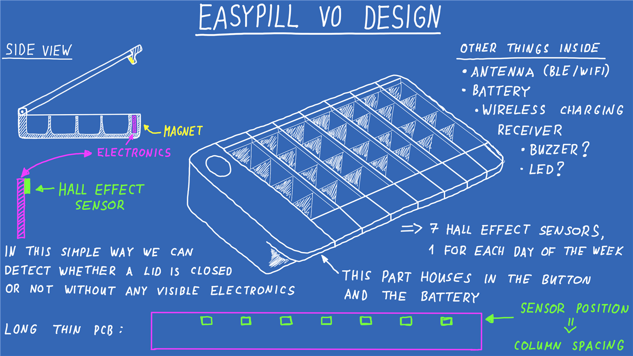
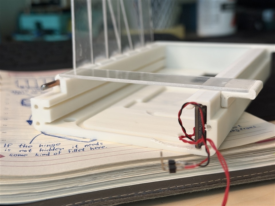
Each of the seven lids contains a small magnet near its hinge. A Hall-effect switch is positioned behind the plastic body directly below it. When the lid is closed, the magnet is close enough to operate the sensor. Opening the lid moves the magnet away and changes the digital signal.
This arrangement avoids exposed microswitches, plungers or metal contacts. There is no mechanical sensor for the user to press, and the magnet does not need to touch the Hall-effect switch. The magnetic field can pass through the thin plastic separating the lid from the PCB.
“You can actually have a piece of plastic between the magnet and the Hall-effect sensor. The magnet doesn’t have to touch the actual package.”
The finished PCB uses seven Diodes Incorporated AH1912 Hall-effect switches. These are omnipolar devices, so either magnetic pole can operate the output. That is useful during assembly because the small magnets do not all need to be installed with a carefully controlled north-south orientation.
The AH1912 is also well suited to a battery-powered enclosure. It operates from 1.6 V to 5.5 V and uses a hibernating internal timing system to achieve an average supply current of approximately 1.6 µA at 3 V. Its output is pulled low when a sufficiently strong magnetic field is detected and returns high once the field falls below its release point.
The result is both physically discreet and electrically simple. A related demonstration of magnetic, non-mechanical switching can be found in the element14 presents project Electronic To-Do List Using Hall Effect Sensors. That project also shows how the choice between unipolar and other Hall-switch behaviours affects the way a magnet operates the circuit.
The Electronics Inside EasyPill
The main controller is a Seeed Studio XIAO ESP32-C3. Its compact footprint and surface-mount-friendly design made it practical to place at one end of the long, narrow PCB, close to the enclosure’s USB opening. The ESP32-C3 provides 2.4 GHz Wi-Fi, Bluetooth Low Energy and a 32-bit RISC-V processor running at up to 160 MHz, with 400 KB of SRAM and 4 MB of flash on the XIAO board. The board measures approximately 21 × 17.8 mm.
For EasyPill, the processing power is less important than the combination of wireless connectivity, compact dimensions and low-power operation. Seeed Studio specifies deep-sleep consumption of approximately 44 µA for the board, although the complete device will consume more once its supporting circuitry and PCB leakage are included.
Miloš originally selected the ESP32-C3 version because it offered lower power consumption than some of the more capable alternatives and the application did not require a more powerful processor. Reviewing the design several years later, however, he would now be inclined to use a complete ESP32 module directly rather than a small development board.
“I would go with an actual module so that I had a bunch of GPIOs. I would also have the 32K crystal and so on, for timekeeping’s sake.”
Using a larger module would provide more direct I/O and could remove some of the multiplexing that made the first revision more complicated. It would also give a future version more control over the radio, low-power configuration and real-time clock behaviour.
Sharing a Small Number of GPIO Pins
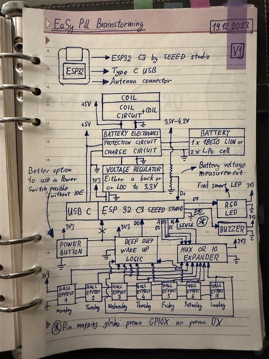
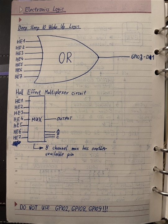
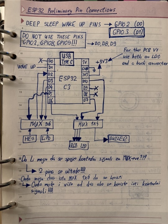
Pin availability was one of the biggest constraints in V0. The board uses three NXP NX3L4051 8:1 analogue multiplexers whose address lines are shared. One multiplexer scans the seven Hall-effect switches, another selects analogue measurements and a third routes output signals for functions including the LED and buzzer.
The NX3L4051 provides eight bidirectional channels and a common input/output, selected using three address inputs. An enable input can place all eight switches into a high-impedance state. It can carry analogue or digital signals and has break-before-make switching, which helps prevent two channels being momentarily connected during a transition.
Sharing the address lines saves GPIO, but it creates a firmware trap. Changing the selected Hall-sensor channel also changes the selected channel on the output multiplexer. If its common output is high while the address changes, that high state can briefly be walked across the MOSFET gates connected to the other channels. The visible result could be a flash from the RGB LED or a short chirp from the buzzer while the firmware is merely trying to scan the lids.
“If you try controlling only one multiplexer, you will change channels on the other ones as well… you would actually just be flashing the LED or the buzzer.”
The firmware deals with this by giving one software component sole ownership of the three address lines. Other parts of the application are not allowed to manipulate them directly. Before selecting a new channel, the output is forced low and given time to settle. Once an operation is complete, the multiplexers are moved to a defined parking channel.
// The one owner of MUX_A/MUX_B/MUX_C.
//
// Those three lines address all three XS3A4051s at once
// (hall input, analog input, output drive), so nothing
// else in the firmware is allowed to touch them.

class MuxBus {
 public:
  void begin();
  void select(uint8_t channel);
  void park();
  void parkForSleep();
};
This centralised approach is important for anybody adapting the design. Treating each multiplexer as an unrelated peripheral would make intermittent output glitches very difficult to diagnose. By concentrating all channel selection in MuxBus, the safety sequence is enforced whenever an input or output is accessed.
The resting channel also changes when the ESP32 enters deep sleep. Under normal operation, channel 7 is used as a safe parking position. During deep sleep, however, holding the associated address pins high would pass current through three 100 kΩ pull-down resistors. The firmware instead selects channel 0 before the ESP32 freezes the GPIO states, avoiding roughly 99 µA of unnecessary sleep current.
That is a small but significant optimisation in a device expected to spend much of its time waiting for somebody to open a lid.
Wake-Up and Soft-Latch Power Control
The seven Hall-effect outputs, button and charging signal feed a hardware wake-up network based on OR gates. A change caused by a lid opening can therefore wake the controller from deep sleep without requiring all seven sensor signals to occupy separate wake-capable GPIO pins.
The main 3.3 V rail uses a soft-latch arrangement. Pressing the external button enables the buck-boost converter and starts the ESP32. Early in the boot process, the firmware asserts a dedicated power-latch GPIO, keeping the converter enabled after the button is released. Pulling that signal low lets the system shut itself down cleanly.
“As soon as you enable the rail, which actually brings up your MCU, it drives this power-latch signal through this diode again. This is how you can actually keep the device on and still turn it on just by using the button.”
The idea worked, although the first PCB requires a modification to the external button path. The battery voltage can be higher than the level tolerated by the ESP32 input, so a 33 kΩ series resistor must be fitted between the button connection and the controller circuitry.
A future revision might omit the user button entirely. With reliable lid-triggered waking and wireless charging, there would be little reason for the normal user to interact with an electronic control.
Battery Charging and Regulation
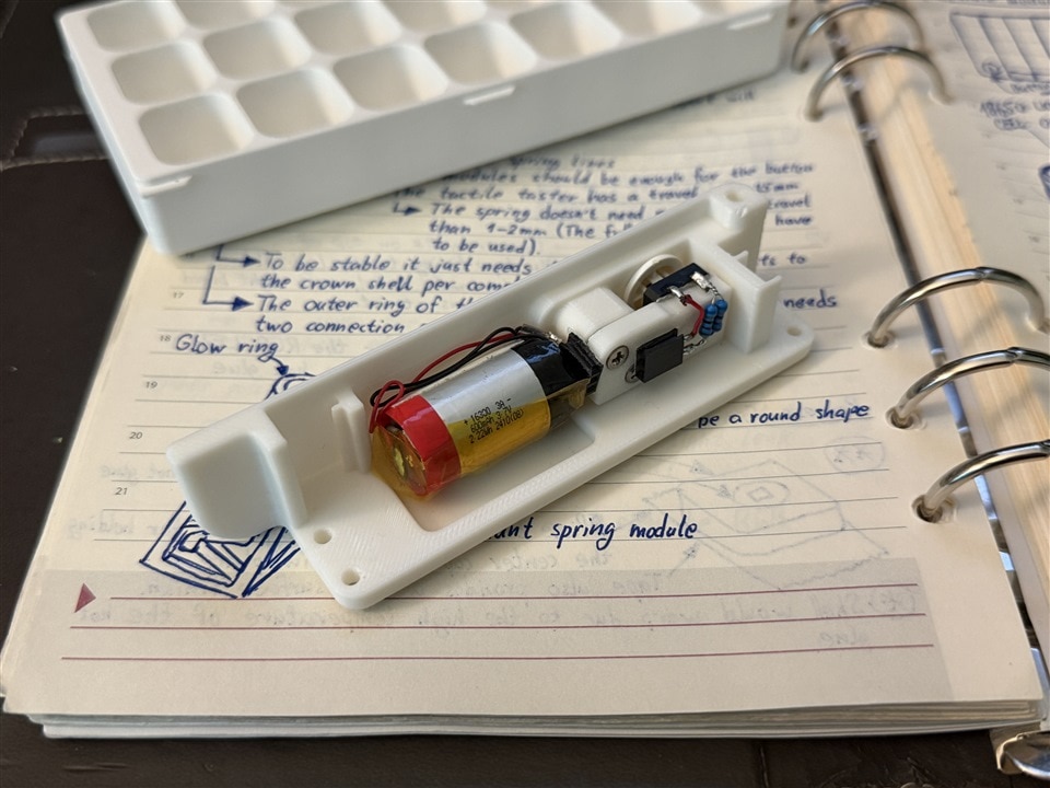
EasyPill is powered by a small single-cell lithium-ion battery fitted in the removable end section. The original design allows the charging input to come from either USB or a 5 V wireless-charging receiver, with Schottky diodes providing basic input OR-ing before the charge controller.
An MCP73831 linear charge controller manages the cell. During bring-up, the programming resistor was changed to 3.3 kΩ to reduce the charging current for the smaller battery eventually installed in the enclosure.
The regulated 3.3 V supply is provided by a TPS63021 buck-boost converter. This lets the circuit maintain its output as the lithium-ion cell moves from above 3.3 V to below it during discharge. Miloš also included an AP7362 3.3 V LDO as a backup because this was his first attempt at assembling the small buck-boost package. In practice, the TPS63021 soldered successfully and operated without difficulty.
The redundant regulator did, however, expose an important PCB-layout error. The ground connection between sections of the board relies on the LDO footprint, so leaving the LDO unpopulated breaks the ground path. A wire must be fitted between the relevant ground pads when the LDO is omitted.
Reviewing and Correcting the First PCB
EasyPill V0 is also an honest review of an older design. Miloš produced the original schematics and PCB in December 2023, but the assembled board remained on his desk for several years. Returning to it with more engineering experience revealed choices he would now handle differently.
The most serious issues are documented rather than hidden:
- The battery-protection circuit is incorrect and must be bypassed by wiring
VBAT_NEGto ground. - The charging-current resistor should be changed to 3.3 kΩ for the smaller battery used in the completed prototype.
- The PCB contains a ground break when the optional LDO is not installed, requiring a wire between its ground connections.
- A 33 kΩ resistor must be added in series with the external button signal to protect the ESP32 input.
- The MOSFET footprints associated with the LED outputs are incorrect.
- Several connectors proved too large for the available enclosure space, so wires were soldered directly to the PCB.
“I’ll note down all of the bodges if you wish to undertake this project as well, just so you don’t have to go around chasing ghosts during your bring-up time.”
The battery-protection error is particularly important. One of the MOSFETs in the protection path is reversed, so the intended circuit cannot be relied upon. Anyone reproducing the board should follow the documented rework rather than assuming that the published first-revision schematic is ready for assembly without modification.
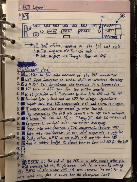
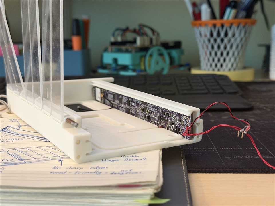
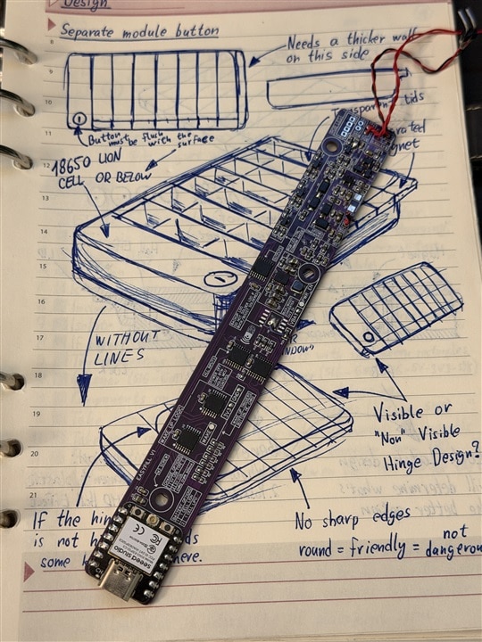
The board is long and narrow because it sits in the strip beneath the line of lid hinges. The XIAO module and USB connector occupy one end, while the multiplexers, power circuitry and battery connections run along the remaining length. Seven Hall-effect switches are positioned on the reverse side at measured intervals corresponding to the seven lids.
Although there is no conventional ground pour on the outer layers, the PCB is a four-layer design with internal ground-reference layers. Miloš also added useful dimensions and labels directly to the board, making it easier to understand how its sensor spacing relates to the enclosure.
With hindsight, he would also move from 0603 passives to at least 0402 components. Smaller packages would release valuable space without making hand assembly unreasonable for someone comfortable with surface-mount soldering.
Designing the Enclosure Around the Electronics
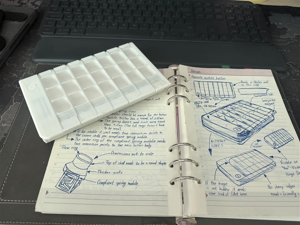
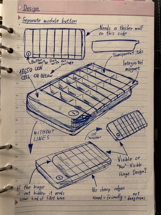
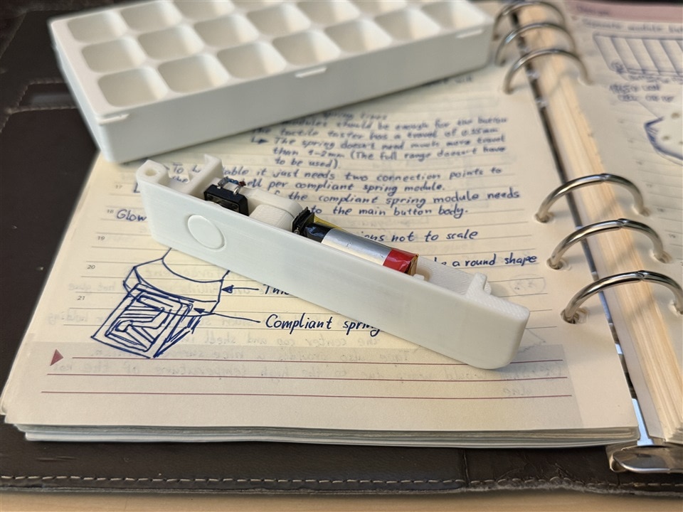
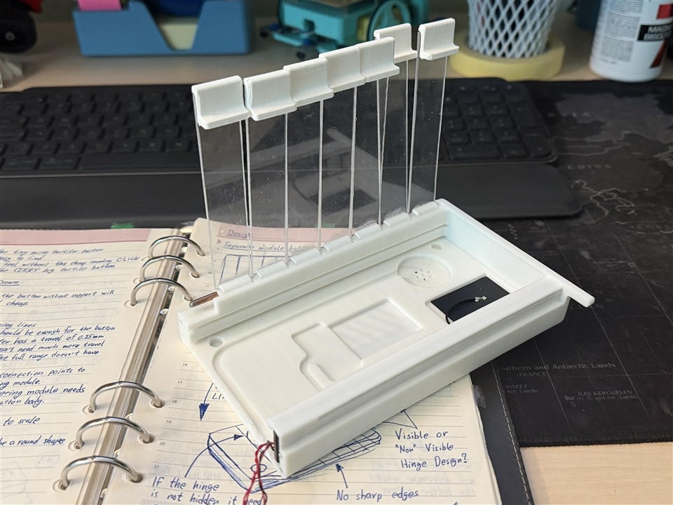
The mechanical design was created in Fusion and intentionally shaped around FDM printing. The finished enclosure remains remarkably close to the sketches Miloš drew in 2023, including the rounded body, seven transparent lids, internal electronics channel and removable end cap.
The main body carries a shared hinge axle for all seven lids. A pocket beneath the hinge accepts the long PCB and aligns each Hall-effect switch with its corresponding magnet. Additional cut-outs provide clearance for the XIAO antenna, buzzer and wireless-charging coil.
The transparent lids could not be produced satisfactorily as normal FDM parts, so each one uses a section cut from 4 mm polycarbonate sheet. The sheet is scored repeatedly with a craft knife and then snapped along the cut. Small printed pieces are bonded to the ends to produce the hinge and magnet holder.
This mixed construction provides a clearer result than printing the complete lid while retaining the ability to manufacture the rest of the enclosure on a typical desktop printer.
The centre tray is removable. The completed prototype uses a 3 × 7 arrangement, giving three compartments for each day, but the same body can accept trays with a different number of medication slots. This is a practical feature because medication routines vary, and redesigning only the insert is easier than rebuilding the sensor system and enclosure.
The end cap holds the battery, external button and supporting hardware. Small M2.5 screws secure the assembly. Miloš would prefer a later version to conceal or eliminate those screws for a more seamless finish, but they make V0 easier to assemble, open and modify while the electronics are still being developed.
Provision was also made for magnetic alignment of a future custom wireless charger. Correct alignment is particularly useful for a small receiving coil because a poorly positioned box may charge slowly or not at all. A future charging base could therefore guide the pillbox into position without adding another visible connector.
Firmware, Scheduling and the Local Dashboard
The firmware is built as a set of separate hardware, scheduling, storage, notification and web-interface components rather than one large application file. The supplied project includes PlatformIO configuration, board pin definitions, Hall scanning, analogue measurement, power-latch control, scheduling, adherence calculations, persistent settings, event storage, notification support and an embedded web application.
The hardware layer keeps the shared multiplexers under central control and converts the seven sensor inputs into stable lid states. The application layer then records when a lid changes and compares that event with the configured medication schedule.
For each scheduled dose, the system can maintain a record containing the expected time, detected time, lid number, dose number and the difference between the scheduled and actual event in minutes. It also distinguishes between pending, taken and missed records rather than treating every lid opening as equivalent.
// Matching lid-open events to scheduled doses, and keeping the record.
//
// A lid-open event proves only that the lid was lifted at a
// particular moment. It does not prove that medication was taken.

uint8_t adherencePercent(
    const Schedule& schedule,
    uint32_t nowLocal,
    uint16_t days,
    uint32_t floorLocal = 0
) const;
The wording in the source is an important reminder of the system’s limits. EasyPill can calculate an interaction-based adherence figure, but that value represents scheduled openings, not clinically verified medication consumption.
The schedule configuration includes a window before and after each expected time, along with a grace period before a dose is marked as missed. The default configuration allows an opening up to 60 minutes before or 120 minutes after the scheduled time, followed by an additional missed-dose grace period. These values are configurable and should be treated as application settings rather than medical guidance.
The software also avoids reporting misleading historical failures. If the device was switched off when a dose was due, that dose is not automatically marked as missed when the box later boots. A normal deep-sleep period is handled differently because the device entered that state with the intention of waking for the next event.
The local dashboard is served directly by the ESP32. It provides:
- A live view of all seven lid states.
- A recent activity and event history.
- The next expected dose.
- Current time and battery information.
- Charging status.
- Medication-schedule configuration.
- Daily and historical interaction records.
- Wi-Fi, device-name and user settings.
- Notification options and shutdown control.
During the demonstration, opening a lid changes the corresponding state on the web page after a short update delay. Because every lid is monitored, the system can also recognise an unusual condition where several or all lids appear open. This could indicate that the box has fallen over, that the tray has been disturbed or that somebody has opened several days while refilling it.
The local interface is intentionally a proof of concept. It demonstrates that the sensing, scheduling and web stack can work together, but it is not presented as a secure internet-facing service.
“None of this really is that good or that secure. This is just a proof of concept, and I just wanted to see it work through the web.”
Anyone developing the idea further should avoid exposing the ESP32 web server directly to the public internet. A production-oriented version would need authenticated access, encrypted transport, protected credential storage, secure provisioning and a considered update mechanism. Medication-related activity can be sensitive personal information even when the device itself does not provide medical advice.
Notifications and Remote Monitoring
The original ambition was to send useful events to family members’ phones. V0 concentrates on proving the mechanical and electrical design, but the firmware already contains support for several notification routes, including ntfy, Pushover and generic webhooks.
Notifications can be selected for events such as:
- A lid being opened.
- A scheduled interaction being recorded.
- An expected interaction being missed.
- A dose becoming due.
- An unexpected lid opening.
- A low battery.
- The device booting.
- A daily summary.
Quiet hours are also included so routine messages do not arrive overnight. A later version could separate urgent events from ordinary activity, for example treating a random midday opening differently from a lid that remains unopened after the configured schedule window.
There is an important distinction between helpful monitoring and excessive surveillance. Frequent raw notifications could become noisy and make genuine problems easier to overlook. A practical deployment would be better served by a small number of meaningful states: expected interaction recorded, expected interaction not recorded, unusual activity and device attention required.
Testing EasyPill
The completed pillbox looks almost entirely non-electronic. The USB opening and small end button are the only obvious clues, and neither is needed during normal interaction with the compartments. Even when the device is running, there is no screen or permanently illuminated status indicator on the box itself.
“You really can’t tell, which is the point. Nothing seems on. It’s just a regular plastic box when it comes to her.”
During testing, each magnet remained close enough to its Hall-effect switch to register the lid as closed through the printed plastic wall. Opening a lid moved the magnet beyond the release threshold, and the web interface updated to show that day as open.
The result fulfils the main V0 objective. It does not confirm that a pill was removed, but it can establish that the box was approached, the correct day was selected and the lid was operated at approximately the expected time.
That information can be especially useful when a family member is away from home. Instead of repeatedly telephoning to ask whether medication has been taken, they can see that an expected interaction occurred. If nothing is recorded, they can then decide whether a reminder or check-in is appropriate.
What Would Change in EasyPill V1?
EasyPill V0 proves the basic proposition, but Miloš identified several areas for a second revision.
The first is sensing. Detecting individual tablets would provide more information than lid monitoring alone, although it will require a method that can tolerate differences in medication size, colour, weight and compartment loading. Any such method would still need to avoid claiming certainty where the sensor can only infer that an object has moved.
An inertial measurement unit could add useful context. A motion interrupt could wake the device when somebody picks it up, while orientation data could help distinguish normal use from the box being dropped or left upside down.
“Whenever somebody picks up the box, maybe it wakes up. It could also check that it’s properly oriented when the lid is open.”
A revised PCB would correct the battery-protection circuit, ground routing, button interface and MOSFET footprints instead of relying on bodge wires. It could use smaller components, a more suitable ESP32 module and enough GPIO to simplify or remove some of the shared multiplexing.
The RGB LED section would also be reconsidered. V0 uses MOSFETs and another multiplexer because pins were scarce, but a compact I²C LED driver would reduce the part count and simplify the firmware. The same review applies to the extensive analogue-monitoring circuitry: useful diagnostic measurements are welcome, but every measurement channel adds cost, board area and software complexity.
Wireless charging remains an attractive option because it could remove the need for routine access to the USB connector. Combined with automatic wake-up, a future box might contain no user-facing electronic controls at all.
The remote side requires further development as well. The proof-of-concept dashboard works on the local network, but a family-monitoring product would need a secure method of carrying selected events beyond that network. Authentication, encryption, reliable timekeeping, offline event storage and safe configuration recovery would all need to be part of that design rather than added as an afterthought.
A Useful Proof of Concept, with Clearly Defined Limits
EasyPill V0 does not try to solve medication management completely. It does something narrower and more achievable: it adds a layer of awareness to an object that many people already use and understand.
The strongest part of the project is not the number of electronic features packed inside the enclosure. It is Miloš’s decision to keep those features out of the user’s way. The person using the pillbox is not asked to navigate menus, read a display, pair a phone or learn a new routine. They continue opening the day’s lid, while the electronics quietly record the interaction.
The build also provides a useful account of engineering iteration. The first PCB contains mistakes, but those errors are identified and documented alongside the working design. The multiplexers save pins but create software constraints. The compact controller fits neatly but contributes to the need for those multiplexers. The Hall-effect switches are unobtrusive but can only report lid state, not whether medication was swallowed.
Those trade-offs define EasyPill V0 honestly. It remains an experimental, non-medical device, but it demonstrates how hidden sensing, low-power wireless electronics, modular 3D-printed mechanics and a small web application can be combined without turning a familiar household object into an intimidating gadget.
“This is anything but a medical device. This is just a concept research project that I had brewing in my mind for years, and I just wanted to bring it to life.”
All of the supporting design files, firmware, web assets, hardware notes and bring-up documentation are provided so that other makers can examine the design, reproduce the prototype and improve on its first revision.
Supporting Files and Links
- Episode 741 Resources - Has Grandma Taken Her Pills? This ESP32 Pillbox Can Help You Find Out
Bill of Materials and Parts Used
| Product Name | Manufacturer | Quantity | Buy Kit |
|---|---|---|---|
| Resistor 100k 1% 0603, CRCW0603100KFKEA | VISHAY | 21 | Buy Now |
| Resistor 330R 1% 0603, CRCW0603330RFKEA | VISHAY | 6 | Buy Now |
| Resistor 75k 1% 0603, CRCW060375K0FKEAC | VISHAY | 4 | Buy Now |
| Resistor 470R 1% 0603, CRCW0603470RFKEAC | VISHAY | 4 | Buy Now |
| Resistor 1M 1% 0603, CRCW06031M00FKEAC | VISHAY | 1 | Buy Now |
| Resistor 2k7 1% 0603, CRCW06032K70FKEA | VISHAY | 1 | Buy Now |
| Resistor 2k 1% 0603, CRCW06032K00FKEA | VISHAY | 1 | Buy Now |
| Capacitor 100nF 50V X7R 0603, MC0603B104K500CT | MULTICOMP PRO | 23 | Buy Now |
| Capacitor 4.7uF 25V X7R 0805, C0805C475K3RACTU | KEMET | 3 | Buy Now |
| Capacitor 10uF 16V X7R 0805, 0805YC106KAT2A | KYOCERA AVX | 3 | Buy Now |
| Capacitor 22uF 6.3V X5R 0805, C0805C226M9PACTU | KEMET | 5 | Buy Now |
| XIAO ESP32-C3 microcontroller board, 113991054 | SEEED STUDIO | 1 | Buy Now |
| LDO regulator 3.3V 1.5A, AP7362-33SP-13 | DIODES INC | 1 | Buy Now |
| Li-ion charge controller, MCP73831T-2ACI/OT | MICROCHIP | 1 | Buy Now |
| 8:1 analogue multiplexer, NX3L4051PW,118 | NXP | 3 | Buy Now |
| Omnipolar hall effect switch, AH1912-W-7 | DIODES INC | 7 | Buy Now |
| Quad 2-input OR gate TSSOP-14, 74LV32APWJ | NEXPERIA | 2 | Buy Now |
| N-channel MOSFET 60V SOT-323, 2N7002BKW,115 | NEXPERIA | 6 | Buy Now |
| Schottky rectifier 40V 3A, RB050LAM-40TR | ROHM | 4 | Buy Now |
| TVS diode 5V 400W SMA, SMAJ5.0A-E3/61 | VISHAY | 1 | Buy Now |
| Power inductor 1.5uH 2.1A 3x3mm, SRN3015-1R5Y | BOURNS | 1 | Buy Now |
Additional Parts
| Product Name | Manufacturer | Quantity |
|---|---|---|
| Buck-boost converter TPS63021DSJR, 3.3 V output, VSON-14, fits U7 | ||
| Li-ion battery protector AP9101CK-AHTRG1, SOT-23-5, fits U11 | ||
| 3D printing filament, White PLA | ||
| Polycarbonate sheet, 4 mm thick, cut to size | ||
| Li-ion cell, Small single cell, reused. Soldered to the U10 pads, pin 1 = + | ||
| M2.5 screws | ||
| Hook-up wire, Leads soldered to the U6, U8, U10, U21 and CTL1 pads |

