element14 Community
element14 Community
    Register Log In
  • Site
  • Search
  • Log In Register
  • About Us
  • Community Hub
    Community Hub
    • What's New on element14
    • Feedback and Support
    • Benefits of Membership
    • Personal Blogs
    • Members Area
    • Achievement Levels
  • Learn
    Learn
    • Ask an Expert
    • eBooks
    • element14 presents
    • Learning Center
    • Tech Spotlight
    • STEM Academy
    • Webinars, Training and Events
    • Learning Groups
  • Technologies
    Technologies
    • 3D Printing
    • FPGA
    • Industrial Automation
    • Internet of Things
    • Power & Energy
    • Sensors
    • Technology Groups
  • Challenges & Projects
    Challenges & Projects
    • Design Challenges
    • element14 presents Projects
    • Project14
    • Arduino Projects
    • Raspberry Pi Projects
    • Project Groups
  • Products
    Products
    • Arduino
    • Avnet Boards Community
    • Dev Tools
    • Manufacturers
    • Multicomp Pro
    • Product Groups
    • Raspberry Pi
    • RoadTests & Reviews
  • Store
    Store
    • Visit Your Store
    • Choose another store...
      • Europe
      •  Austria (German)
      •  Belgium (Dutch, French)
      •  Bulgaria (Bulgarian)
      •  Czech Republic (Czech)
      •  Denmark (Danish)
      •  Estonia (Estonian)
      •  Finland (Finnish)
      •  France (French)
      •  Germany (German)
      •  Hungary (Hungarian)
      •  Ireland
      •  Israel
      •  Italy (Italian)
      •  Latvia (Latvian)
      •  
      •  Lithuania (Lithuanian)
      •  Netherlands (Dutch)
      •  Norway (Norwegian)
      •  Poland (Polish)
      •  Portugal (Portuguese)
      •  Romania (Romanian)
      •  Russia (Russian)
      •  Slovakia (Slovak)
      •  Slovenia (Slovenian)
      •  Spain (Spanish)
      •  Sweden (Swedish)
      •  Switzerland(German, French)
      •  Turkey (Turkish)
      •  United Kingdom
      • Asia Pacific
      •  Australia
      •  China
      •  Hong Kong
      •  India
      •  Korea (Korean)
      •  Malaysia
      •  New Zealand
      •  Philippines
      •  Singapore
      •  Taiwan
      •  Thailand (Thai)
      • Americas
      •  Brazil (Portuguese)
      •  Canada
      •  Mexico (Spanish)
      •  United States
      Can't find the country/region you're looking for? Visit our export site or find a local distributor.
  • Translate
  • Profile
  • Settings
Ben Heck Featured Content
  • Challenges & Projects
  • element14 presents
  • element14's The Ben Heck Show
  • Ben Heck Featured Content
  • More
  • Cancel
Ben Heck Featured Content
Forum Engine Management
  • Blog
  • Forum
  • Documents
  • Events
  • Polls
  • Files
  • Members
  • Mentions
  • Sub-Groups
  • Tags
  • More
  • Cancel
  • New
Join Ben Heck Featured Content to participate - click to join for free!
Actions
  • Share
  • More
  • Cancel
Forum Thread Details
  • Replies 63 replies
  • Subscribers 46 subscribers
  • Views 4146 views
  • Users 0 members are here
Related

Engine Management

jack.chaney56
jack.chaney56 over 9 years ago

Hi Ben,

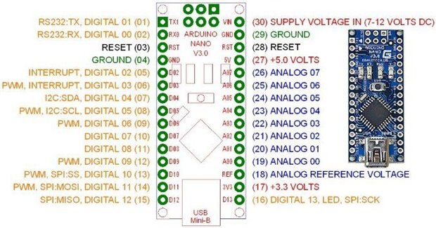
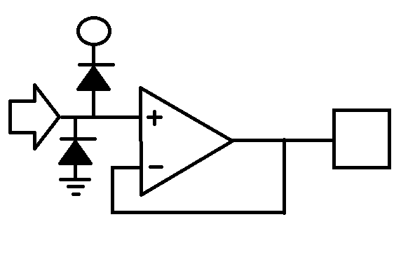
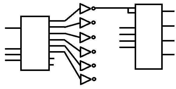
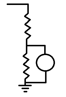
I am a programmer with a very small amount of skill with circuits, and am looking to create a platform for an engine management system, using an Arduino Mega 2560. I had done a bit of the coding, when I ran into some timing issues with the built in Arduino manager, so I switched over and started using AVR Studio and a programmer to go directly to the chip itself.  The code looks like it should work ok, but now I need some additional circuits to handle the energy levels of coils and injectors (Something like IGBTs). Sensors are being run through simple dividers (no protection yet), and cam and crank inputs are through a simple comparitor


Let me know what you think,

Jack

  • Sign in to reply
  • Cancel

Top Replies

  • jack.chaney56
    jack.chaney56 over 7 years ago +2
    Back again... After a bit of time away seeking enlightenment (and a steady paycheck), I am ready to get back to work on my project. I have continued to play around with the code and a number of components…
  • jack.chaney56
    jack.chaney56 over 7 years ago +2
    I want to start this thing right, so the shopping list for people that want to play along at home: Raspberry Pi - version is not significant if you don't mind a slow response when using Eclipse, but 3B…
  • jack.chaney56
    jack.chaney56 over 7 years ago +2
    Start off with two things. First, I forgot (neglected) to provide instruction on how to get the compiled code onto the Nano. Fault of familiarity; having done the process so many times, I had shifted to…
Parents
  • jack.chaney56
    jack.chaney56 over 7 years ago

    I was going to run the code when I got home from my real job. Then, I started setting up my bench, connecting up all the parts, and plugging in the power, sat back in my chair, and blinked. Three hours later, my wife told me I would probably be more comfortable sleeping in bed.  So, I didn't get a chance to compile all this stuff, and I don't have my bench set up here at work. I can provide a few extras in order to move things along, like circuits. People here seem to like circuits.


    The Nano has a bunch of pins to connect the 328 to the outside world.

    image

    I am not an Electrical Engineer, but I have had a lot of experience dealing with circuits and circuit design (mostly at the logic level), and things I throw together on a breadboard tend to work, so please understand any circuits I provide, would do well to have a serious design overview performed.


    image

    With that in mind... the Nano has two sets of connecters on either side of the board. One side is primarily the A/Ds, and the other side is listed as D0 - D13. For the project, the D0 and D1 will remain reserved for serial communication (works through the USB), D2 and D3 will be the interrupt inputs for crank and cam signals (this will be circuit 1). D4 through D11 will operate the output latches (this will be circuit 2). The analog lines are tricky, and open to all sorts of opinion, so I will offer a simple solution, and let people with more knowledge make comment (circuit 3).


    Circuit 1: The circle is for 12v Vbatt (should have a resistor to regulate. The arrow is the crank or cam signal (same circuit for both). The box is the line that goes to either D2 or D3 depending. The IC is just a simple comparator (like an LM2903).

    image

    Circuit 2: The box on the left is a 74ls138, the input lines go from top to bottom D7 (enable), D4 (A0), D5 (A1), and D6 (A2). The outputs route through a 74ls04 hex inverter. The inverter connects to the enable 1&2 and enable 3&4 of the 75ls75 (one of 6 shown). The other inputs of the 74ls75 are connected to D8 (1D), D9 (2D), D10 (3D), and D11 (4D). The D8-D11 connect the same to all 6 of the 74ls75 ICs. If you would like, you can add another 04 and two more 75s and have 32 output lines, but 24 is satisfactory for this application.

    image

    Circuit 3: Analog lines are all similar and only need to provide a simple divider. The sensors that are attached are the governing elements here. The simple divider is shown. Where the circle represents some sort of variable resistance sensor, and the line on the left attaches to the A/D input. Though looking at this, it probably needs a pull up resistor someplace. Again, just a play circuit for now.

    image

    • Cancel
    • Vote Up +2 Vote Down
    • Sign in to reply
    • Cancel
Reply
  • jack.chaney56
    jack.chaney56 over 7 years ago

    I was going to run the code when I got home from my real job. Then, I started setting up my bench, connecting up all the parts, and plugging in the power, sat back in my chair, and blinked. Three hours later, my wife told me I would probably be more comfortable sleeping in bed.  So, I didn't get a chance to compile all this stuff, and I don't have my bench set up here at work. I can provide a few extras in order to move things along, like circuits. People here seem to like circuits.


    The Nano has a bunch of pins to connect the 328 to the outside world.

    image

    I am not an Electrical Engineer, but I have had a lot of experience dealing with circuits and circuit design (mostly at the logic level), and things I throw together on a breadboard tend to work, so please understand any circuits I provide, would do well to have a serious design overview performed.


    image

    With that in mind... the Nano has two sets of connecters on either side of the board. One side is primarily the A/Ds, and the other side is listed as D0 - D13. For the project, the D0 and D1 will remain reserved for serial communication (works through the USB), D2 and D3 will be the interrupt inputs for crank and cam signals (this will be circuit 1). D4 through D11 will operate the output latches (this will be circuit 2). The analog lines are tricky, and open to all sorts of opinion, so I will offer a simple solution, and let people with more knowledge make comment (circuit 3).


    Circuit 1: The circle is for 12v Vbatt (should have a resistor to regulate. The arrow is the crank or cam signal (same circuit for both). The box is the line that goes to either D2 or D3 depending. The IC is just a simple comparator (like an LM2903).

    image

    Circuit 2: The box on the left is a 74ls138, the input lines go from top to bottom D7 (enable), D4 (A0), D5 (A1), and D6 (A2). The outputs route through a 74ls04 hex inverter. The inverter connects to the enable 1&2 and enable 3&4 of the 75ls75 (one of 6 shown). The other inputs of the 74ls75 are connected to D8 (1D), D9 (2D), D10 (3D), and D11 (4D). The D8-D11 connect the same to all 6 of the 74ls75 ICs. If you would like, you can add another 04 and two more 75s and have 32 output lines, but 24 is satisfactory for this application.

    image

    Circuit 3: Analog lines are all similar and only need to provide a simple divider. The sensors that are attached are the governing elements here. The simple divider is shown. Where the circle represents some sort of variable resistance sensor, and the line on the left attaches to the A/D input. Though looking at this, it probably needs a pull up resistor someplace. Again, just a play circuit for now.

    image

    • Cancel
    • Vote Up +2 Vote Down
    • Sign in to reply
    • Cancel
Children
  • mp2100
    mp2100 over 7 years ago in reply to jack.chaney56

    Jack.

    Yes, please. Pay attention to what your wife says. It will make the results better for you, everyone. :-)

    • Cancel
    • Vote Up +1 Vote Down
    • Sign in to reply
    • Cancel
  • mp2100
    mp2100 over 7 years ago in reply to jack.chaney56

    Still trying to catch up with all the details but I'm enjoying reading thru it all.  I  want to encourage your postings.  I'm not in the automotive industry but chemical industry. It's all kind of the same and all a bit different.

    • Cancel
    • Vote Up +1 Vote Down
    • Sign in to reply
    • Cancel
  • jack.chaney56
    jack.chaney56 over 7 years ago in reply to jack.chaney56

    I thought I would clean things up a bit...

    Attachments:
    imageE14_ECM.pdf
    • Cancel
    • Vote Up +1 Vote Down
    • Sign in to reply
    • Cancel
element14 Community

element14 is the first online community specifically for engineers. Connect with your peers and get expert answers to your questions.

  • Members
  • Learn
  • Technologies
  • Challenges & Projects
  • Products
  • Store
  • About Us
  • Feedback & Support
  • FAQs
  • Terms of Use
  • Privacy Policy
  • Legal and Copyright Notices
  • Sitemap
  • Cookies

An Avnet Company © 2025 Premier Farnell Limited. All Rights Reserved.

Premier Farnell Ltd, registered in England and Wales (no 00876412), registered office: Farnell House, Forge Lane, Leeds LS12 2NE.

ICP 备案号 10220084.

Follow element14

  • X
  • Facebook
  • linkedin
  • YouTube