element14 Community
element14 Community
    Register Log In
  • Site
  • Search
  • Log In Register
  • Community Hub
    Community Hub
    • What's New on element14
    • Feedback and Support
    • Benefits of Membership
    • Personal Blogs
    • Members Area
    • Achievement Levels
  • Learn
    Learn
    • Ask an Expert
    • eBooks
    • element14 presents
    • Learning Center
    • Tech Spotlight
    • STEM Academy
    • Webinars, Training and Events
    • Learning Groups
  • Technologies
    Technologies
    • 3D Printing
    • FPGA
    • Industrial Automation
    • Internet of Things
    • Power & Energy
    • Sensors
    • Technology Groups
  • Challenges & Projects
    Challenges & Projects
    • Design Challenges
    • element14 presents Projects
    • Project14
    • Arduino Projects
    • Raspberry Pi Projects
    • Project Groups
  • Products
    Products
    • Arduino
    • Avnet & Tria Boards Community
    • Dev Tools
    • Manufacturers
    • Multicomp Pro
    • Product Groups
    • Raspberry Pi
    • RoadTests & Reviews
  • About Us
  • Store
    Store
    • Visit Your Store
    • Choose another store...
      • Europe
      •  Austria (German)
      •  Belgium (Dutch, French)
      •  Bulgaria (Bulgarian)
      •  Czech Republic (Czech)
      •  Denmark (Danish)
      •  Estonia (Estonian)
      •  Finland (Finnish)
      •  France (French)
      •  Germany (German)
      •  Hungary (Hungarian)
      •  Ireland
      •  Israel
      •  Italy (Italian)
      •  Latvia (Latvian)
      •  
      •  Lithuania (Lithuanian)
      •  Netherlands (Dutch)
      •  Norway (Norwegian)
      •  Poland (Polish)
      •  Portugal (Portuguese)
      •  Romania (Romanian)
      •  Russia (Russian)
      •  Slovakia (Slovak)
      •  Slovenia (Slovenian)
      •  Spain (Spanish)
      •  Sweden (Swedish)
      •  Switzerland(German, French)
      •  Turkey (Turkish)
      •  United Kingdom
      • Asia Pacific
      •  Australia
      •  China
      •  Hong Kong
      •  India
      •  Korea (Korean)
      •  Malaysia
      •  New Zealand
      •  Philippines
      •  Singapore
      •  Taiwan
      •  Thailand (Thai)
      • Americas
      •  Brazil (Portuguese)
      •  Canada
      •  Mexico (Spanish)
      •  United States
      Can't find the country/region you're looking for? Visit our export site or find a local distributor.
  • Translate
  • Profile
  • Settings
Ben Heck Featured Content
  • Challenges & Projects
  • element14 presents
  • element14's The Ben Heck Show
  • Ben Heck Featured Content
  • More
  • Cancel
Ben Heck Featured Content
Forum Components
  • Blog
  • Forum
  • Documents
  • Events
  • Polls
  • Files
  • Members
  • Mentions
  • Sub-Groups
  • Tags
  • More
  • Cancel
  • New
Join Ben Heck Featured Content to participate - click to join for free!
Actions
  • Share
  • More
  • Cancel
Forum Thread Details
  • Replies 17 replies
  • Subscribers 43 subscribers
  • Views 1123 views
  • Users 0 members are here
  • arduino
Related

Components

sekrit_skworl
sekrit_skworl over 10 years ago

I can't find a single place online which covers almost all components and explains their function on video.


I have struggled for a week (aside the 2 days spent in the hospital) trying to understand how transistors I work...  I am constantly attempting to learn.


Please create a YouTube playlist to teach us these things.


Thank You

  • Sign in to reply
  • Cancel

Top Replies

  • michaelkellett
    michaelkellett over 10 years ago +3
    I think you'll need to be prepared to read stuff as well as use video. Most of the tutorial material I see on YouTube is very weak. Give us an idea of the level you are at and I'll attempt to suggest some…
  • michaelkellett
    michaelkellett over 10 years ago in reply to sekrit_skworl +2
    A simple transistor amplifier: This is an explanation for beginners, it is not the whole truth but this way of thinking about transistors (or to be pedantic Bipolar Junction Transistors) will work for…
  • nick123
    nick123 over 10 years ago +1
    Use google. , try this playlist https://www.youtube.com/watch?v=MVy_MG0X2h4&list=PLA9212719342ED971
Parents
  • nick123
    nick123 over 10 years ago

    Use google. image, try this playlist https://www.youtube.com/watch?v=MVy_MG0X2h4&list=PLA9212719342ED971

    • Cancel
    • Vote Up +1 Vote Down
    • Sign in to reply
    • Cancel
  • sekrit_skworl
    sekrit_skworl over 10 years ago in reply to nick123

    Nick!!!...Dude!!!!... Really awesome that you replied.  You're the only one who has not thrown any useless comments at me on the internet so far.  I really appreciate it.  :-D


    That video made a lot of sense for use as a switch.  The main thing that I am unclear of however was unfortunately not covered.  How are transistors used for amplification?

    • Cancel
    • Vote Up 0 Vote Down
    • Sign in to reply
    • Cancel
  • nick123
    nick123 over 10 years ago in reply to sekrit_skworl

    The small audio signal turns the transistor on and off really fast which lets the higher voltage go low and high fast enough so that it reproduces the sound only louder because of the higher voltage. If that didn't make any sense check out these videos. They helped me when I didn't understand transistors. image I know what it's like to not understand transistors. You look everywhere online, you ask everyone on forums, it's a pain.


    https://www.youtube.com/watch?v=mDUTTLCM2K8

    https://www.youtube.com/watch?v=W8hqr5X5ii0


    Tell me if you have anymore questions image

    Nick

    • Cancel
    • Vote Up +1 Vote Down
    • Sign in to reply
    • Cancel
  • clem57
    clem57 over 10 years ago in reply to sekrit_skworl

    Transistors are the pulleys of the mechanical world. They use small current to allow more current to flow through semiconductors. In fact these are essential for modern day computers using billions to make a chip like Intel.

    • Cancel
    • Vote Up 0 Vote Down
    • Sign in to reply
    • Cancel
  • sekrit_skworl
    sekrit_skworl over 10 years ago in reply to nick123

    Nick, somehow I missed your second post yesterday. I watched them last night, and they were both extremely helpful.  I believe that I now grasp the general concept.


    However, looking at the diagrams, I see things labeled as "input".  Is "Input" supposed to be positive or negative?  You noted something about "Audio Signals" earlier, but I have no knowledge of audio or anything else yet.


    I am simply attempting to understand basics before ripping open a breadboard to start trying things as I learn. :-)

    • Cancel
    • Vote Up 0 Vote Down
    • Sign in to reply
    • Cancel
  • nick123
    nick123 over 10 years ago in reply to sekrit_skworl

    Well, an audio signal is positive and negative. It is like the AC power in your house. Its alternating so the answer is both. Positive and Negative.

    Here is another video.


    https://www.coursera.org/course/audiomusicengpart1

    • Cancel
    • Vote Up +1 Vote Down
    • Sign in to reply
    • Cancel
  • clem57
    clem57 over 10 years ago in reply to nick123

    Sorry Nick this does not ring true  (pun intended). From Wikipedia:


    Audio signals are sound waves—longitudinal waves which travel through air, consisting of compressions and rarefactions

    But if you are talking about analog signals, I can agree partially what you say. Again from wikipedia:


    Thus, an analog signal is one represented by a continuous stream of data, in this case along an electrical circuit in the form of voltage, current or charge changes (compare with digital signals below). Analog signal processing (ASP) then involves physically altering the continuous signal by changing the voltage or current or charge via various electrical means.

    Since either voltage or current can change can change. If you look at electrical circuits it is important to note which way some components affect the electrical characteristics (voltage or current).


    Check out https://en.wikipedia.org/wiki/Audio_signal_processing for more details since I only used some of the material here.


    Thanks,

    Clem

    • Cancel
    • Vote Up +1 Vote Down
    • Sign in to reply
    • Cancel
  • nick123
    nick123 over 10 years ago in reply to clem57

    Oh, I guess your right. Sorry.

    • Cancel
    • Vote Up +1 Vote Down
    • Sign in to reply
    • Cancel
  • sekrit_skworl
    sekrit_skworl over 10 years ago in reply to clem57

    Ok gentlemen,


    This poses a conundrum for me...

    ...I am looking at wiring diagrams.  So, if they alternate, and either anode or cathode can be connected to trigger the transistor base, which one should I connect, and what should I do with the other lead?


    If possible, I would like to deal with just electrical without getting into specific audio, video, or other specific application fields.  Audio Jacks have more than one wire, so I wouldn't be able to understand which wire goes where when discussing signals yet.


    I apologize for this inconvenience, and truly appreciate both of you (Nick & Clem).


    However, please continue (noting the exclusion request) as I am learning more about transistor usage in the past 24 hours from you guys and your links, than any Google search that I have tried...


    ...I promise that I wasn't too lazy to ask.  It seems as though I didn't know enough to request results which would return responses to meet my needs (Like looking at a dog, commanding it to google doggie treats, and expecting it to work out as I would prefer LOL... And, yes, I would be the clueless dog in this analogy.)


    Thanks again guys for the continued support.

    • Cancel
    • Vote Up 0 Vote Down
    • Sign in to reply
    • Cancel
Reply
  • sekrit_skworl
    sekrit_skworl over 10 years ago in reply to clem57

    Ok gentlemen,


    This poses a conundrum for me...

    ...I am looking at wiring diagrams.  So, if they alternate, and either anode or cathode can be connected to trigger the transistor base, which one should I connect, and what should I do with the other lead?


    If possible, I would like to deal with just electrical without getting into specific audio, video, or other specific application fields.  Audio Jacks have more than one wire, so I wouldn't be able to understand which wire goes where when discussing signals yet.


    I apologize for this inconvenience, and truly appreciate both of you (Nick & Clem).


    However, please continue (noting the exclusion request) as I am learning more about transistor usage in the past 24 hours from you guys and your links, than any Google search that I have tried...


    ...I promise that I wasn't too lazy to ask.  It seems as though I didn't know enough to request results which would return responses to meet my needs (Like looking at a dog, commanding it to google doggie treats, and expecting it to work out as I would prefer LOL... And, yes, I would be the clueless dog in this analogy.)


    Thanks again guys for the continued support.

    • Cancel
    • Vote Up 0 Vote Down
    • Sign in to reply
    • Cancel
Children
  • nick123
    nick123 over 10 years ago in reply to sekrit_skworl

    Can you show us the diagram you are looking at?

    (Sorry if we are over complicating things...)

    • Cancel
    • Vote Up +1 Vote Down
    • Sign in to reply
    • Cancel
  • sekrit_skworl
    sekrit_skworl over 10 years ago in reply to nick123

    Please don't apologize, you guys are AWESOME!  And, I appreciate both of your patience. :-D


    I am inserting an image of a diagram with an input as directed.

    Attachments:
    image
    • Cancel
    • Vote Up 0 Vote Down
    • Sign in to reply
    • Cancel
  • michaelkellett
    michaelkellett over 10 years ago in reply to sekrit_skworl

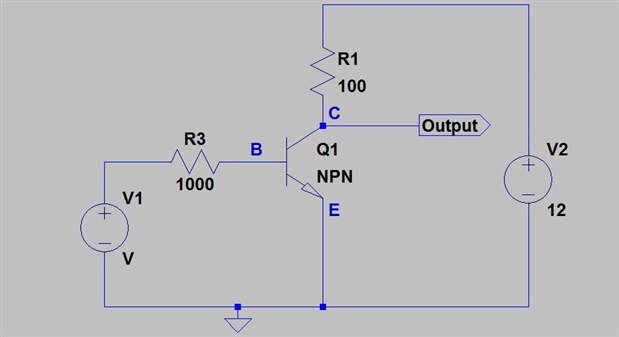
    A simple transistor amplifier:


    image

    This is an explanation for beginners, it is not the whole truth but this way of thinking about transistors (or to be pedantic Bipolar Junction


    Transistors) will work for most DC circuits.


    This is an NPN transistor (PNP works the same except all the voltages go the other way round, in my reality current flows from Positivie to Negative


    which is called Conventional Current  - some people get all excited about what the electrons are doing but you don't need to know.)


    The first thing you need to know is that the transistor will only work properly when it has some current flowing in it and something is making sure that


    there is a voltage from collector to emitter and base to emitter. This is called biasing the transistor and is essential to make them work with AC in


    linear circuits (switching circuits are a bit different and we'll worry about them another day.)


    So in our circuit we make V1 the input voltage 1V.

    V2 is the 12V power supply and the little triangle is the zero or ground reference point.

    The base to emitter connection in the transistor is like a diode so if we make the base positive then current wants to flow from base to emitter and it


    can (the diode part of the symbol shows that). There is a a way of working out exactly what the voltage across the base emitter needs to be for any


    current but for starters we'll just say that for small silicon transistors you'll get about 600mV for reasonable currents.


    The 1V input will give us a current of (1 - 0.6)/1000 = 0.4mA.

    (That's the applied voltage - the base/emitter voltage divided by the total resistance in the loop = 1000 ohms).


    Now we come to the magical part of transistors.


    If you make a current flow from base to emitter the transistor will try to make a bigger current flow from collector to emitter.


    The collector current divided by the base current is the transistor gain (often Hfe or HFE in data sheets (warning  - economy with truth here)).


    A typical gain for a small transistor would be 100 so our Q1 will try to make 0.4 * 100 = 40mA flow in it's collector.


    This will have to flow through R1 so the voltage across R1 will be 100 * 0.04 = 4V so the output voltage will be 12 - 4 = 8V from the ground reference.


    If we change the voltage on V1 to 1.1V the current in the base emitter circuit will increase to 0.5mA so the collector current will increase to 50mA and


    the voltage across R1 will be 5V so the output voltage will drop to 7V


    So for a change of +0.1V on the input the output changed by -1V.


    This amplifier has a gain of -10, it will only work for a small range of input voltages (it won't work at all if the input voltage is zero).


    It's not a very good amplifier because its very dependent on the gain of the transistor (and in real life that often varies by 2:1 or more) and that


    assumption about 0.6V across the base emitter is OK in better circuits but makes this one even worse.


    A useful amplifier is a bit more complicated.


    If this level of description is useful I'll do some more later (might be a week or so 'coz I'm going on hols tomorrow).


    MK

    • Cancel
    • Vote Up +2 Vote Down
    • Sign in to reply
    • Cancel
  • sekrit_skworl
    sekrit_skworl over 10 years ago in reply to michaelkellett

    Ok, first thing Michael... Thank You for adding to the tutelage pool to assist me on this.  SECOND, enjoy a happy holiday! :-D


    Ok, so, looking at the circuit and description:


    1a.) Assuming V2 to be a 12V battery, is V1 drawing from V2?


    1b.) If so, what caused the transition from 12V to 1V?

    • Cancel
    • Vote Up 0 Vote Down
    • Sign in to reply
    • Cancel
  • michaelkellett
    michaelkellett over 10 years ago in reply to sekrit_skworl

    V1 is completely independent of V2.

    This is an imaginary circuit so it can contain voltage sources and current sources. In real life such things don't exist but they are useful (essential) in analysing how things work.


    A voltage source is a two terminal device that maintains a defined voltage across its terminals. It's a bit like a very good battery. In real life there are no true voltage sources.


    So in this circuit V1 is the input and we don't need to worry where it comes from or how it's made.

    V2 is the power supply and we just accept for now that it's 12V.


    Later on - when we get nearer to a useful circuit, we might need to improve our model of the input source.


    Really am off now !


    MK

    • Cancel
    • Vote Up +1 Vote Down
    • Sign in to reply
    • Cancel
  • sekrit_skworl
    sekrit_skworl over 10 years ago in reply to michaelkellett

    Thank you so much, please have fun.


    In the meantime, could someone please explain to me the effect of ground on a circuit?  Or, simply verify whether:


    1.) Ground cuts current in half or does it reduce current in another manner?


    2.) diagrams with ground are simply a grounded electrical plug?

    • Cancel
    • Vote Up 0 Vote Down
    • Sign in to reply
    • Cancel
element14 Community

element14 is the first online community specifically for engineers. Connect with your peers and get expert answers to your questions.

  • Members
  • Learn
  • Technologies
  • Challenges & Projects
  • Products
  • Store
  • About Us
  • Feedback & Support
  • FAQs
  • Terms of Use
  • Privacy Policy
  • Legal and Copyright Notices
  • Sitemap
  • Cookies

An Avnet Company © 2025 Premier Farnell Limited. All Rights Reserved.

Premier Farnell Ltd, registered in England and Wales (no 00876412), registered office: Farnell House, Forge Lane, Leeds LS12 2NE.

ICP 备案号 10220084.

Follow element14

  • X
  • Facebook
  • linkedin
  • YouTube