element14 Community
element14 Community
    Register Log In
  • Site
  • Search
  • Log In Register
  • Community Hub
    Community Hub
    • What's New on element14
    • Feedback and Support
    • Benefits of Membership
    • Personal Blogs
    • Members Area
    • Achievement Levels
  • Learn
    Learn
    • Ask an Expert
    • eBooks
    • element14 presents
    • Learning Center
    • Tech Spotlight
    • STEM Academy
    • Webinars, Training and Events
    • Learning Groups
  • Technologies
    Technologies
    • 3D Printing
    • FPGA
    • Industrial Automation
    • Internet of Things
    • Power & Energy
    • Sensors
    • Technology Groups
  • Challenges & Projects
    Challenges & Projects
    • Design Challenges
    • element14 presents Projects
    • Project14
    • Arduino Projects
    • Raspberry Pi Projects
    • Project Groups
  • Products and Partners
    Products and Partners
    • Arduino
    • Avnet & Tria Boards Community
    • Dev Tools
    • Manufacturers
    • Multicomp Pro
    • Product Groups
    • Raspberry Pi
    • RoadTests & Reviews
  • About Us
    About the element14 Community
  • Store
    Store
    • Visit Your Store
    • Choose another store...
      • Europe
      •  Austria (German)
      •  Belgium (Dutch, French)
      •  Bulgaria (Bulgarian)
      •  Czech Republic (Czech)
      •  Denmark (Danish)
      •  Estonia (Estonian)
      •  Finland (Finnish)
      •  France (French)
      •  Germany (German)
      •  Hungary (Hungarian)
      •  Ireland
      •  Israel
      •  Italy (Italian)
      •  Latvia (Latvian)
      •  
      •  Lithuania (Lithuanian)
      •  Netherlands (Dutch)
      •  Norway (Norwegian)
      •  Poland (Polish)
      •  Portugal (Portuguese)
      •  Romania (Romanian)
      •  Russia (Russian)
      •  Slovakia (Slovak)
      •  Slovenia (Slovenian)
      •  Spain (Spanish)
      •  Sweden (Swedish)
      •  Switzerland(German, French)
      •  Turkey (Turkish)
      •  United Kingdom
      • Asia Pacific
      •  Australia
      •  China
      •  Hong Kong
      •  India
      •  Japan
      •  Korea (Korean)
      •  Malaysia
      •  New Zealand
      •  Philippines
      •  Singapore
      •  Taiwan
      •  Thailand (Thai)
      •  Vietnam
      • Americas
      •  Brazil (Portuguese)
      •  Canada
      •  Mexico (Spanish)
      •  United States
      Can't find the country/region you're looking for? Visit our export site or find a local distributor.
  • Translate
  • Profile
  • Settings
element14's The Ben Heck Show
  • Challenges & Projects
  • element14 presents
  • element14's The Ben Heck Show
  • More
  • Cancel
element14's The Ben Heck Show
Forum Viewer Challenge - iPhone 360 Controller
  • Blog
  • Forum
  • Documents
  • Polls
  • Files
  • Members
  • Mentions
  • Sub-Groups
  • Tags
  • More
  • Cancel
  • New
Join element14's The Ben Heck Show to participate - click to join for free!
Actions
  • Share
  • More
  • Cancel
Forum Thread Details
  • Replies 22 replies
  • Subscribers 29 subscribers
  • Views 1761 views
  • Users 0 members are here
Related

Viewer Challenge - iPhone 360 Controller

e14 Contributor
e14 Contributor over 16 years ago

You're the master of hardware, but how about software?


I challenge you to build an app for the iPhone that will work in conjunction with a small chip-based converter that will allow the iPhone's touch screen to work as a controller for an Xbox 360. It can connect either wired over the standard USB connection for the 360, or, for a real challenge, wirelessly over the Bluetooth standard connection

  • Sign in to reply
  • Cancel
  • e14 Contributor
    e14 Contributor over 16 years ago

    That's not possible due to our friend encryption, but I have an alternate that I'm trying to figure out but can't.


    So, I want to try to make a game-playing piece of software, where I point a camera at an HDTV or framegrab a screen, determine what the best move is through the magic of pattern recognition and AI, and then control a gamepad to make the move.


    I'm not an EE and my electronics experience is mostly troubleshooting and modifying arcade games (aside, I run http://coinop.org) from the 80s with a scope and/or logic probe and replacing chips that aren't working right anymore after analyzing the circuit against a schematic, things like that. So I've always used stuff that's already been designed to interact with other circuits, or is self contained. I have scars from a time when I was a child and I tried to interface a modem with a C64 data port and blew up two C64s because of what is likely this very problem.


    I want to open up an XBOX 360 controller and have the computer simulate button presses (the controllers use some kind of encryption so I can't just emulate the controller directly). So I guess I need some kind of driver board to "short" the switches together.


    I have one of these


    http://www.ultimarc.com/pacdrive.html


    It's an LED driver, but it seems like I might be able to wire up one side of each switch in the controller to accomplish this? It's just an 8 output board. But, how do you deal with the different grounds? The wiring diagram with the 12V external power source doesn't make sense to me, as the 12V source is over there and you're using the + but you're going back to - over here in this other place. It seems to think in the comment that you're going to run the 12V from the power supply in the same computer with the USB so that would probably make sense that way but in this case I have two different devices with two different supplies.


    So here's the crux:


    The Controller has a USB cable and is hooked up to device A (xbox).
    The board has a USB cable and is hooked up to device B (computer).


    The USB shield grounds ont he two devices have different ground potentials.So in this case, i tried using 4016s with inverters, but no dice. I wonder if the voltage difference is too great on the 74HC 4066 on the controller side since the controller is 2.4V internally and the USB on the other board is 5v. The circuit with the 74HC 4066 works, on the logic side I'm pulling up to 5v, do I need to do something similar on the controller side? Is there a better way to do this?


    Do I need optocouplers?


    I mean the board I have is essentially a selectable 8 output board, and it selects outputs properly, and I can control that in software and measure it.


    But it doesn't register button presses on the keypad. if I just short the two wires together that I have soldered to the pad, it works fine.


    Sigh.

    • Cancel
    • Vote Up 0 Vote Down
    • Sign in to reply
    • Cancel
  • e14 Contributor
    e14 Contributor over 15 years ago

    Interesting idea but why? Surely you've played games on the iPhone/iPod Touch, touch screen only works well for basic games, I would imagine it would be terrible at implementing a d-pad, 6 push buttons, two triggers and two thumbsticks. If you want basic functionality for menus and dvds just get a remote image


    It would be possible to do but I reckon you would have a dismember a 360 pad to wire up to the receiving end to do all the comms between the pad and the 360.

    Edit - Just re-read post above and what he said image

    • Cancel
    • Vote Up 0 Vote Down
    • Sign in to reply
    • Cancel
  • e14 Contributor
    e14 Contributor over 15 years ago in reply to e14 Contributor

    From the front page it says you can run up to 500mA without external power - provided by the usb. This should be more than enough, all you should have to do is wire a ground between the USB board and the 360 pad then check which side of the button pad is +V and wire the USB board output to the other pad - simulating the connection to +V pad. From a quick look I don't see why that shouldn't work image

    • Cancel
    • Vote Up 0 Vote Down
    • Sign in to reply
    • Cancel
  • e14 Contributor
    e14 Contributor over 15 years ago in reply to e14 Contributor

    I think I explained myself poorly. I want to write software on my PC to analyze screen capture of the 360, process if there's a move to make, and then make the move via the controller. No touch screen involved. This is for actual gameplay, not menus.


    I also thought it would work the way you outlined, and that was my first try. It doesn't work that way, it doesn't work with the 4066 equivalents, and now I guess it's on to the optos.

    • Cancel
    • Vote Up 0 Vote Down
    • Sign in to reply
    • Cancel
  • e14 Contributor
    e14 Contributor over 15 years ago in reply to e14 Contributor

    Sorry that first response was to Eric about the iPhone 360 pad. I  get what you're saying about your idea - sounds quite complex and I'd definitely like to see the outcome.

    I've got a 360 pad with a dodgy thumbstick so I'll crack that open see what I can make of it.

    • Cancel
    • Vote Up 0 Vote Down
    • Sign in to reply
    • Cancel
  • e14 Contributor
    e14 Contributor over 15 years ago in reply to e14 Contributor

    After a little probing it's clear that there is more going on that switching between 0 and 5v, how did you wire the 4066's? If you used both sides of the pads for each it shouldn't be a problem, if you wired one side to 5v or ground and the other to the pad that would be the problem. If not then a little more investigating will be needed image

    • Cancel
    • Vote Up 0 Vote Down
    • Sign in to reply
    • Cancel
  • e14 Contributor
    e14 Contributor over 15 years ago in reply to e14 Contributor

    The output from the driver board goes into an enable line, with a pullup. That part works perfectly. The two pad lines are on the other side of the 4066. No dice. I think cos the pad side is 2.4v and the other side is 5v and the 4066 uses a transistor, there's too different a voltage diff. I think the optos are needed? What's funny is I've talked to 3 EEs and I had one here and no dice. This shouldn't be that hard, should it?

    • Cancel
    • Vote Up 0 Vote Down
    • Sign in to reply
    • Cancel
  • e14 Contributor
    e14 Contributor over 15 years ago in reply to e14 Contributor

    Or maybe I just need pulldowns on the controller side since they are going low. But I shouldn't have to if I have the two sides of the same pad on that side, and yet that doesn't work.

    • Cancel
    • Vote Up 0 Vote Down
    • Sign in to reply
    • Cancel
  • e14 Contributor
    e14 Contributor over 15 years ago in reply to e14 Contributor

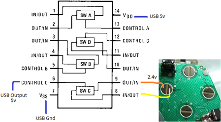
    Just to clarify you have it wired like the image or have tried it like that?

    image

    The voltage doesn't matter because the transistor is acting as a switch you could switch it on with 5v and be switching 100v on the other side, theoretically.

    If you haven't tried without the pullup/downs I would try that. I don't see why it wouldn't work unless the switching frequency of the signal is higher than the switch will pass?

    A couple of captures I took earlier:

        imageimage

    Which explain why switching 5v doesn't work image

    • Cancel
    • Vote Up 0 Vote Down
    • Sign in to reply
    • Cancel
  • e14 Contributor
    e14 Contributor over 15 years ago in reply to e14 Contributor

    Yeah that's right, that's exactly right. I'm using a pullup on the control side, and I figured I wouldn't need anything on the other side. I know that transistors have a drop across them, no? And maybe if the drop is 1.2 volts or whatever, and the source is 2.4v, that it's dropping too much? that's all I can think of with that.


    As far as the switching frequency, I'm switching via software and the control side, and leaving it. It switches and I immediately see a change to high on the other side (the board goes low and I'm using an inverter). If I meter the out/in pins on the other side, there is no continuity when off, and continuity when on. However, if I have the controller pads wired to the in/out, nothing happens. However, if I just short the wires together everything's fine. It's sort of baffling.


    What's up with the three pulses? Those are generated on one button press? I'm actually using a madcatz arcade style controller board, and I'm able to short the pad together. I have a gamepad tester (run joy.cpl on vista/7 and probably xp to see that), which is where i'm doing my testing. When I short the wires together I see the red light light up and stay lit. When I do it in circuit, nothing happens.

    • Cancel
    • Vote Up 0 Vote Down
    • Sign in to reply
    • Cancel
>
element14 Community

element14 is the first online community specifically for engineers. Connect with your peers and get expert answers to your questions.

  • Members
  • Learn
  • Technologies
  • Challenges & Projects
  • Products
  • Store
  • About Us
  • Feedback & Support
  • FAQs
  • Terms of Use
  • Privacy Policy
  • Legal and Copyright Notices
  • Sitemap
  • Cookies

An Avnet Company © 2026 Premier Farnell Limited. All Rights Reserved.

Premier Farnell Ltd, registered in England and Wales (no 00876412), registered office: Farnell House, Forge Lane, Leeds LS12 2NE.

Follow element14

  • X
  • Facebook
  • linkedin
  • YouTube