element14 Community
element14 Community
    Register Log In
  • Site
  • Search
  • Log In Register
  • About Us
  • Community Hub
    Community Hub
    • What's New on element14
    • Feedback and Support
    • Benefits of Membership
    • Personal Blogs
    • Members Area
    • Achievement Levels
  • Learn
    Learn
    • Ask an Expert
    • eBooks
    • element14 presents
    • Learning Center
    • Tech Spotlight
    • STEM Academy
    • Webinars, Training and Events
    • Learning Groups
  • Technologies
    Technologies
    • 3D Printing
    • FPGA
    • Industrial Automation
    • Internet of Things
    • Power & Energy
    • Sensors
    • Technology Groups
  • Challenges & Projects
    Challenges & Projects
    • Design Challenges
    • element14 presents Projects
    • Project14
    • Arduino Projects
    • Raspberry Pi Projects
    • Project Groups
  • Products
    Products
    • Arduino
    • Avnet Boards Community
    • Dev Tools
    • Manufacturers
    • Multicomp Pro
    • Product Groups
    • Raspberry Pi
    • RoadTests & Reviews
  • Store
    Store
    • Visit Your Store
    • Choose another store...
      • Europe
      •  Austria (German)
      •  Belgium (Dutch, French)
      •  Bulgaria (Bulgarian)
      •  Czech Republic (Czech)
      •  Denmark (Danish)
      •  Estonia (Estonian)
      •  Finland (Finnish)
      •  France (French)
      •  Germany (German)
      •  Hungary (Hungarian)
      •  Ireland
      •  Israel
      •  Italy (Italian)
      •  Latvia (Latvian)
      •  
      •  Lithuania (Lithuanian)
      •  Netherlands (Dutch)
      •  Norway (Norwegian)
      •  Poland (Polish)
      •  Portugal (Portuguese)
      •  Romania (Romanian)
      •  Russia (Russian)
      •  Slovakia (Slovak)
      •  Slovenia (Slovenian)
      •  Spain (Spanish)
      •  Sweden (Swedish)
      •  Switzerland(German, French)
      •  Turkey (Turkish)
      •  United Kingdom
      • Asia Pacific
      •  Australia
      •  China
      •  Hong Kong
      •  India
      •  Korea (Korean)
      •  Malaysia
      •  New Zealand
      •  Philippines
      •  Singapore
      •  Taiwan
      •  Thailand (Thai)
      • Americas
      •  Brazil (Portuguese)
      •  Canada
      •  Mexico (Spanish)
      •  United States
      Can't find the country/region you're looking for? Visit our export site or find a local distributor.
  • Translate
  • Profile
  • Settings
element14's The Ben Heck Show
  • Challenges & Projects
  • element14 presents
  • element14's The Ben Heck Show
  • More
  • Cancel
element14's The Ben Heck Show
Forum Burglar Alarm to Door Buzzer Using a Monostable Circuit
  • Blog
  • Forum
  • Documents
  • Polls
  • Files
  • Members
  • Mentions
  • Sub-Groups
  • Tags
  • More
  • Cancel
  • New
Join element14's The Ben Heck Show to participate - click to join for free!
Actions
  • Share
  • More
  • Cancel
Forum Thread Details
  • Replies 32 replies
  • Subscribers 29 subscribers
  • Views 2715 views
  • Users 0 members are here
  • monostable
Related

Burglar Alarm to Door Buzzer Using a Monostable Circuit

Former Member
Former Member over 10 years ago

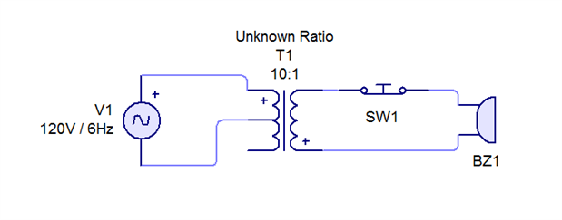
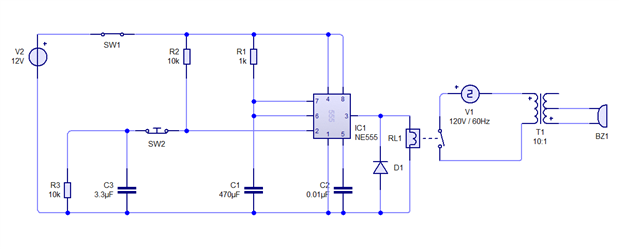
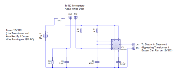
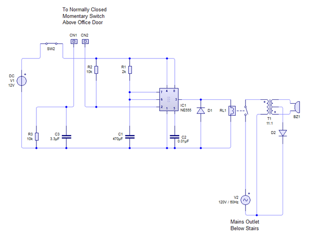
At work we are currently using what I suspect is a burglar alarm as a door buzzer. It's inappropriately loud to have buzzing the entire time the door is ajar (from barely open onward), as we're a motel and it's frankly obnoxious. However in order to hear people come in from the basement, it's what the folks in charge decided to use. I would very much like to create a monostable circuit so it buzzes for a small amount of time then turns off until the door is shut again, re-arming the buzzer. The buzzer works using a momentary switch that is pressed when the door is shut and released when the door is open. This switch is connected to what looks like a transformer core, and the device also plugs into our AC outlet.


I have looked at circuits online, but even using a few simulators I was unable to produce results like I wanted. Can I have some advice? I'm new to electrical engineering.

  • Sign in to reply
  • Cancel

Top Replies

  • jw0752
    jw0752 over 10 years ago +1
    Hi Simon, I have set up a mock up of an improved circuit which allows the door switch to close and remain closed. The components that I have selected for C1 and R1 give a time of approximately 5 seconds…
  • jw0752
    jw0752 over 10 years ago in reply to Former Member

    Hi Simon, It is nothing complicated. When the relay coil turns off the magnetic field creats a voltage in the opposite direction. The diode provides a path for the voltage to dissipate so that it can't hurt the 555 timer. Here is a picture.

    John


    image

    • Cancel
    • Vote Up 0 Vote Down
    • Sign in to reply
    • Cancel
  • jw0752
    jw0752 over 10 years ago in reply to Former Member

    Sorry about the size of that schematic. I will try something different.

    John


    image

    • Cancel
    • Vote Up 0 Vote Down
    • Sign in to reply
    • Cancel
  • Former Member
    Former Member over 10 years ago

    For the curious, I drew a diagram of what I saw at work. This circuit is connected in a manner that fits my drawing, more or less (I don't know about the transformer connections exactly) and behaves the same as the circuit at work.


    image

    Here is my current circuit, which I believe behaves as intended: a ballpark 1 second pulse to the relay when the door is shut after opening it. Having this happen when the door is initially opened would be perfect but this is good. I am curious whether or not the placement and bias of my diode is correct, because my simulator doesn't show me the expected feedback. The transformer section is less than important as the buzzer already functions when connected to the mains outlet.


    image

    • Cancel
    • Vote Up 0 Vote Down
    • Sign in to reply
    • Cancel
  • jw0752
    jw0752 over 10 years ago in reply to Former Member

    Yes, your schematic looks good to me. I think you will find that your button on the door is open when the door is closed and closed when the door is opened so it will work just as planned. Buzzer should ring for about a half a second because of the R1 C1 values and then go quiet until the door is closed and reopened. Also be aware that the C3 value of 3.3 uF is not critical, a 2uF to a 5uF will still work the same. Your protection diode is drawn correctly and unless your simulator is quite sophisticated it may not recognize its purpose but it is important. When you wire this up be very careful with the mains voltage. It might be better to put your relay switch in the seconday just like the door switch is presently placed so that you do not have to bring mains voltage to the circuit board.

    John

    • Cancel
    • Vote Up 0 Vote Down
    • Sign in to reply
    • Cancel
  • Former Member
    Former Member over 10 years ago

    This is (yet another) diagram.


    image

    As the buzzer is currently hooked up to a transformer of unknown ratio, it may be possible to run 12V through the circuit using that transformer and a rectifier setup and pass it (minus about 1.7V) to the buzzer. That's dependent on it working with DC of course. Since it's a magnetic bell hammer I've assumed it will for now. Thanks for the feedback on my progression. (I never mentioned it, but SW2 in this diagram and the related switch in others is an on/off switch for ease of toggling.)

    • Cancel
    • Vote Up 0 Vote Down
    • Sign in to reply
    • Cancel
  • jw0752
    jw0752 over 10 years ago in reply to Former Member

    Hi Simon, No, the 555 can supply at the most 200 mA which will not power the buzzer. It is better to get a low current relay as you drew before and let the relay fit into the place of your present door switch and leave the transformer and the rest of the buzzer circuit alone. You will have to get power for the 555 circuit but you can use a 12 volt DC wall adapter which will safely provide that power. All you will have to do is make sure you connect the positive lead from the wall adapter to the 12V + of the circuit board. You are on the right track.

    John

    • Cancel
    • Vote Up 0 Vote Down
    • Sign in to reply
    • Cancel
  • Former Member
    Former Member over 10 years ago

    Relay it is. I keep putting more than 1W through the simulated buzzer and destroying it (no idea what the real one can handle). The transformer seemed to be building up voltage, but with this configuration it does not. Am I the only one who thinks the transformer reverse connections are odd? Maybe it's a common thing to do.


    image

    • Cancel
    • Vote Up 0 Vote Down
    • Sign in to reply
    • Cancel
  • jw0752
    jw0752 over 10 years ago in reply to Former Member

    Hi Simon, Your present real life transformer buzzer arrangement has proven functionality. I would not change anything there except to use the relay for the switch in place of the door switch which will go to triggering the 555 circuit. The D-2 in your latest schematic is a mistake and should not be used as it will tie your low voltage to your mains. I would put the relay switch into the circuit on the same side of the transformer as the buzzer and leave the transformer hooked directly to the mains. I am not sure but this is probably the way it is hooked up in your present real life application as it is the safest and most professional way to hook it up. The transformer relay part of the circuit does not have polarity ( + signs ) as it is AC.  At this point don't worry about the power handling ability of the buzzer as your simulation buzzer may not accurately emulate the real one. I also see that you have upped the R-1 to give yourself about 1 second of buzzer when the door is open. This is probably a good idea. Now it is time to get your schematic approved and build it. I am looking forward to good results.

    John

    • Cancel
    • Vote Up 0 Vote Down
    • Sign in to reply
    • Cancel
  • Former Member
    Former Member over 10 years ago in reply to jw0752

    What do you mean by "use the relay for the switch in place of the door switch"? I'm hesitant to mess with the door switch, as it took three iterations for the electrician to get one that was reliable installed. They would work for a few times then stop working, and the current one has remained working.

    • Cancel
    • Vote Up 0 Vote Down
    • Sign in to reply
    • Cancel
  • jw0752
    jw0752 over 10 years ago in reply to Former Member

    Sorry if I confused the issue. Leave the door switch as it is in the door but run the wires from it to the switch position in our schematic. Run the wires from the relay contacts to the position in the old door bell circuit where the door switch was originally. Here is a revised and completed schematic of how your system should look.

    John


    image

    • Cancel
    • Vote Up 0 Vote Down
    • Sign in to reply
    • Cancel
<>
element14 Community

element14 is the first online community specifically for engineers. Connect with your peers and get expert answers to your questions.

  • Members
  • Learn
  • Technologies
  • Challenges & Projects
  • Products
  • Store
  • About Us
  • Feedback & Support
  • FAQs
  • Terms of Use
  • Privacy Policy
  • Legal and Copyright Notices
  • Sitemap
  • Cookies

An Avnet Company © 2025 Premier Farnell Limited. All Rights Reserved.

Premier Farnell Ltd, registered in England and Wales (no 00876412), registered office: Farnell House, Forge Lane, Leeds LS12 2NE.

ICP 备案号 10220084.

Follow element14

  • X
  • Facebook
  • linkedin
  • YouTube